Preface
Adopting advanced CNC technology and automatic control systems, the CNC machine for submersible oil motor assembly features precise programming and intelligent operation procedures. The machine improves assembly efficiency and product quality while reducing operational risks, but also reduce manual operation risks. The machine helps enterprises achieve high-efficiency and low-cost production, and enhances their market competitiveness.
1.Machine Structure
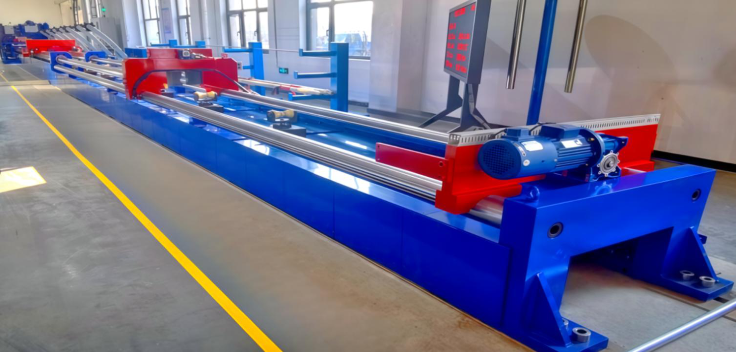
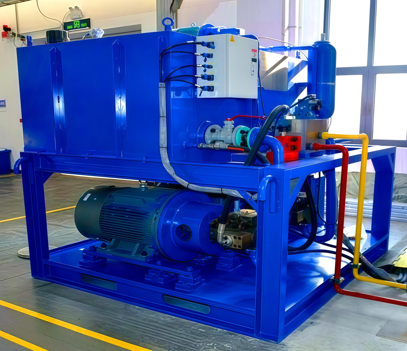
The machine consists of the main machine structure,hydraulic power system, electrical control system and other components.(SeeFigure1~Figure3)
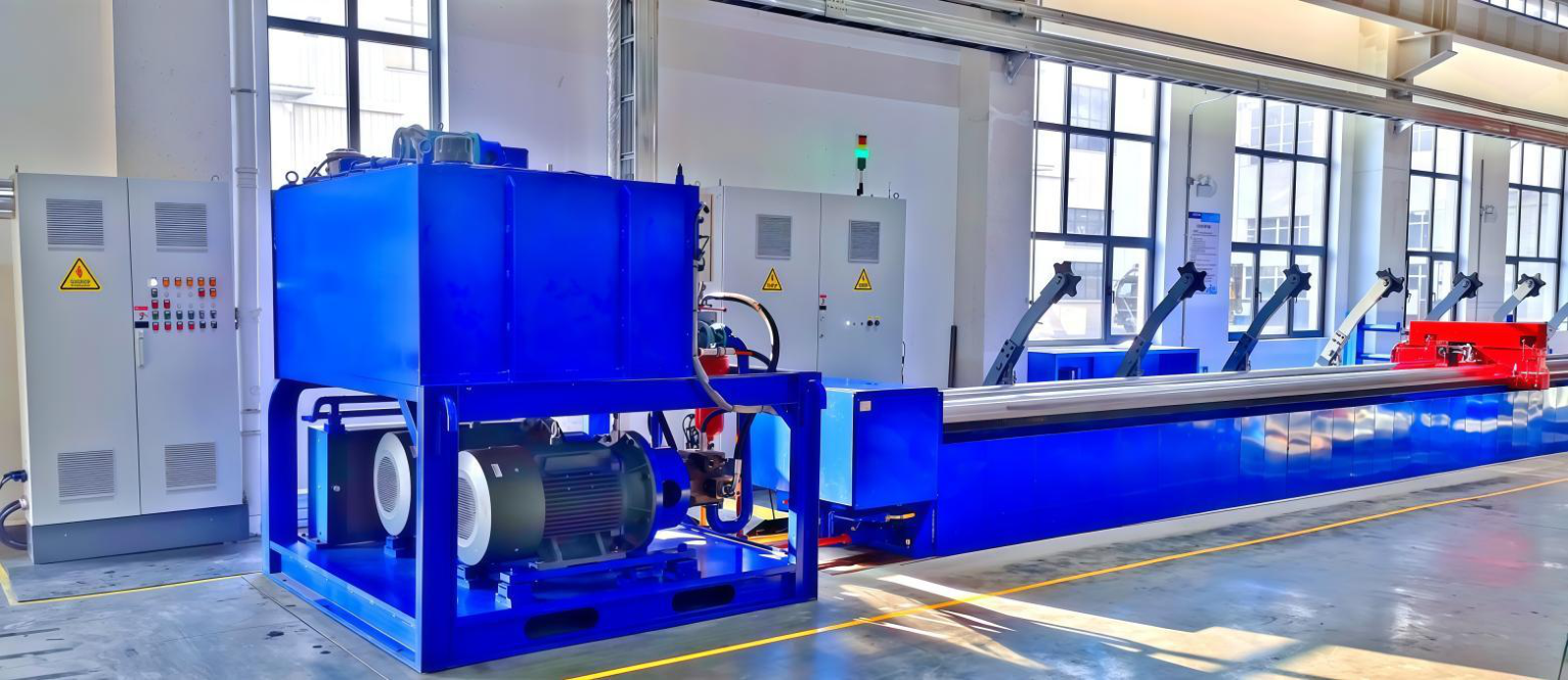
Figure 1 Main Machine Body
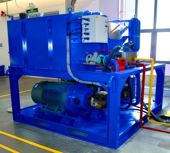
Figure 2 Hydraulic System
Figure 3 Electric Control System
2.Applicable Product Specifications & Assembly Process
2.1 Applicable Specification Dimensions of Submersible Oil Motors
| Series |
Outer Diameter
of Motor Housing(mm)
|
Minimum Length(m) |
Maximum Length(m) |
Lamination Outer
Diameter(mm)
|
Lamination Inner
Diameter(mm)
|
| 375 |
96 |
1.59 |
6.45 |
95.25 |
52 |
| 456 |
116 |
1.52 |
9.62 |
115.8 |
62 |
| 456D |
116 |
1.76 |
9.6 |
115.8 |
62 |
| 540 |
138 |
1.62 |
9.3 |
137.16 |
72 |
| 562 |
143 |
1.94 |
9.5 |
142.75 |
71 |
| 562D |
143 |
1.94 |
10.49 |
142.75 |
71 |
| 738 |
187 |
1.6 |
9.51 |
187.4 |
100 |
2.2 Machine Assembly Process Flow(SeeFigure4)
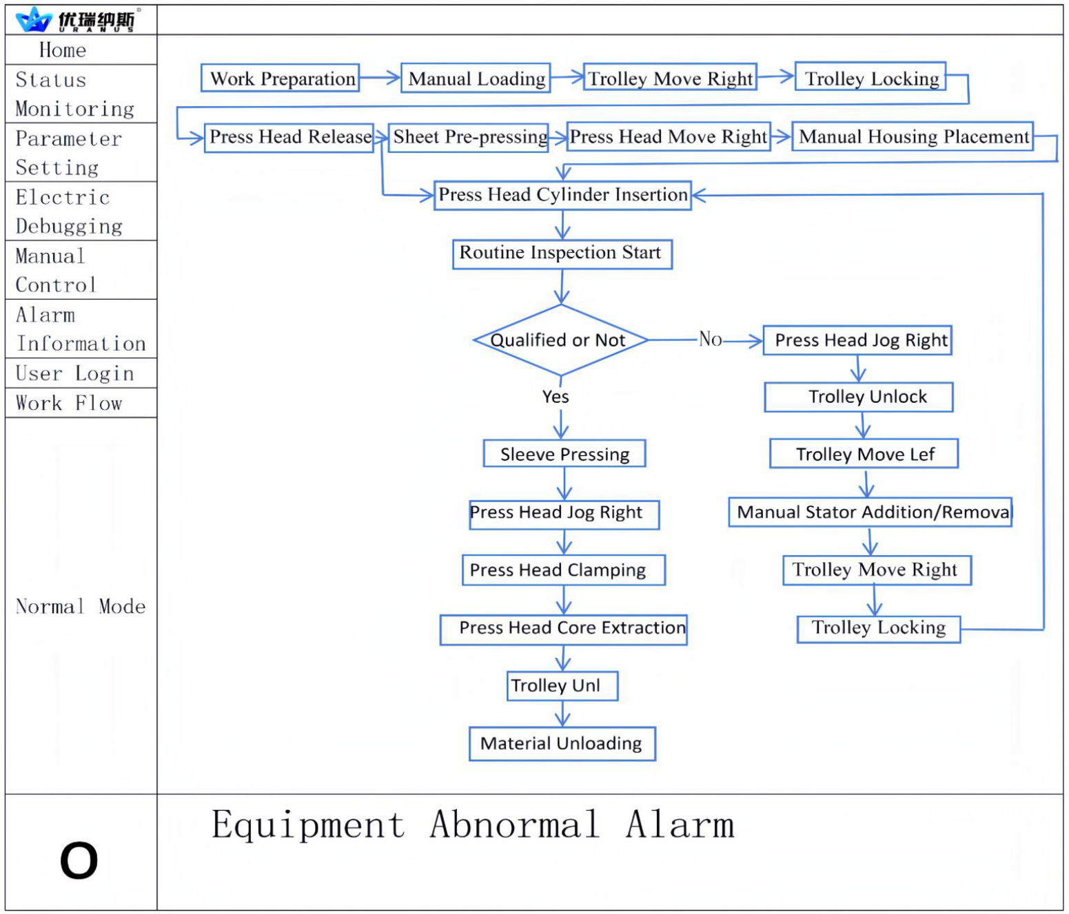
Figure 4 Assembly Process Flow of Submersible Oil Motor
3.Technical Parameters & Functions of Main Components
3.1 Main Machine Body(See Figure 5)
The main machine body is composed of ground rails,machine bed,pushing cylinder,clamping device,jacking trolley,core withdrawing device,pressure head, rail lifting device and other parts.Overall dimension(L×W×H):24000×1800×1900 mm;Total weight:about 34 tons
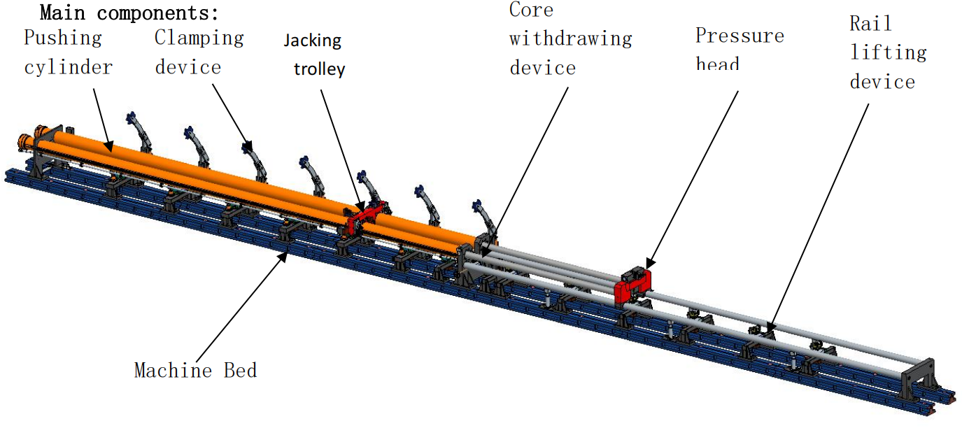
Figure 5.Main Machine Structure
3.1.1 Machine Bed
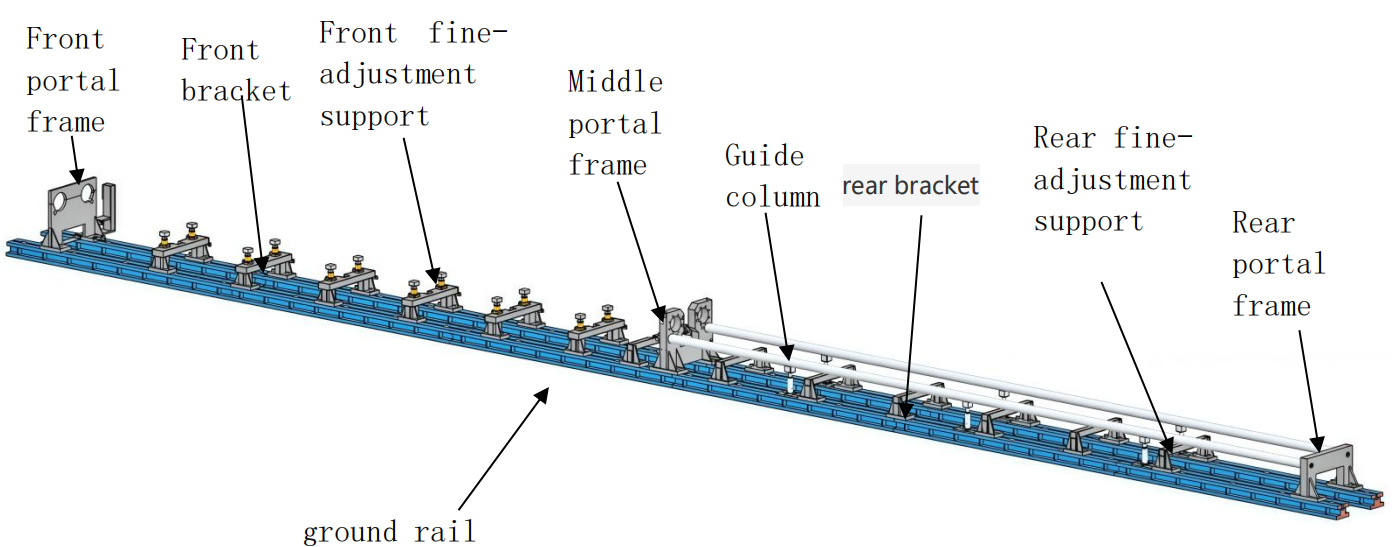
Composed of 12 sets of ground rails,3 portal frames,2 guide columns,7 sets of front brackets,6 sets of rear brackets,12 sets of front fine-adjustment supports and 6 sets of rear fine-adjustment supports.Dimension(L×W×H):24000×1400×1100 mm(including ground rails,excluding foundation);Total weight:about 19 tons.(See Figure 6 Main Structure)
Figure 6 Components
The ground rail serves as the horizontal reference, load-bearing and force bearing foundation of the whole equipment, and is poured into the concrete foundation. All portal frames and brackets are directly installed on the ground rails. Both ends of the guide columns are fixed on the middle and rear portal frames. Fine-adjustment supports are mounted on the brackets.
3.1.2 Sets of Pushing Servo Hydraulic Cylinders
The pushing cylinder provides the main power for submersible oil motor assembly. Two pushing cylinders are installed between the front portal frame and middle portal frame, supported by 12 sets of front fine-adjustment supports at the bottom.Dimension (L×W×H): 11600×400×310 mm; Single cylinder weight: about 3.3 tons.(See Figure 7)


Figure7 3D Drawing & Physical Photo of Main Thrust Servo Hydraulic Cylinders
Performance parameters:Stroke: 11000 mm; Thrust: 500 KN; Pulling Force: 250 kN; Extension Speed: 100 mm/s, all continuously adjustable as required. Equipped with magnetic linear encoder and proportional valve to form a closed loop. The PLC controls synchronous operation of double cylinders, with follow-up synchronous error ≤ 5 mm and stop position synchronous error ≤ 2 mm. A rack is mounted on the outer sleeve of the pushing cylinder to serve as the running track for the jacking trolley.
3.1.3 Jacking Trolley
The Pressing Carriage is mounted on the cylinder barrel of the two pushing oil cylinders.Dimension (L×W×H): 1424×736×602 mm; Total weight: about 562 KG. It is composed of trolley frame, traveling mechanism, locking mechanism, distance measuring device and sleeving driving device.(See Figure 8)
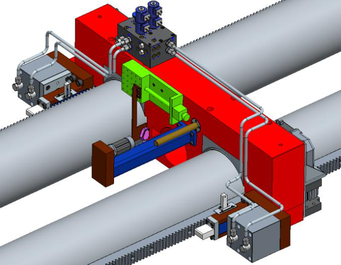
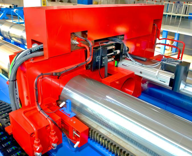
Figure 8 3D Drawing & Physical Photo of Jacking Trolley
Functions of Pressing Carriage:
1).Before pre-pressing and lamination pressing of the submersible oil motor stator,one end is locked by its built-in mechanisms to prevent the motor from sliding whenthe pushing cylinder applieslaminating pressure to the other end via the pressurehead.
2).The built-in laser displacement sensor automatically measures the thickness of
the stator core.
3).After the motor stator is clamped, the electric cylinder drives the retainingring into the clamping groove of the motor housing.
3.1.4 Pressure Head
The pressure head mainly consists of support sleeves sleeved on two guidecolumns, left-right moving doors, as well as servo motor, reducer, gear and rackmechanism for opening and closing the moving doors.(See Figure 9)
Driven by the pushing cylinder, the pressure head slides back and forth alongthe guide columns.
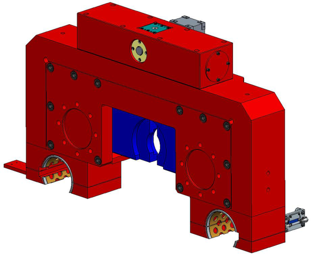
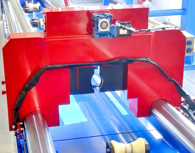
Figure 9 3D Drawing & Physical Photo of Pressure Head
Functions of Pressure Head:
1).Driven by the pushing cylinder, the closed moving door of the pressure head performs lamination pressing on stator iron sheets.
2).Driven by the pushing cylinder, the movable clamping plates clamps the mandrel and pulls it out from the motor housing.
3.1.5 Clamping Device
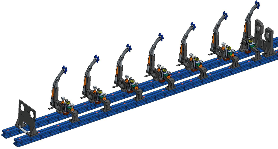
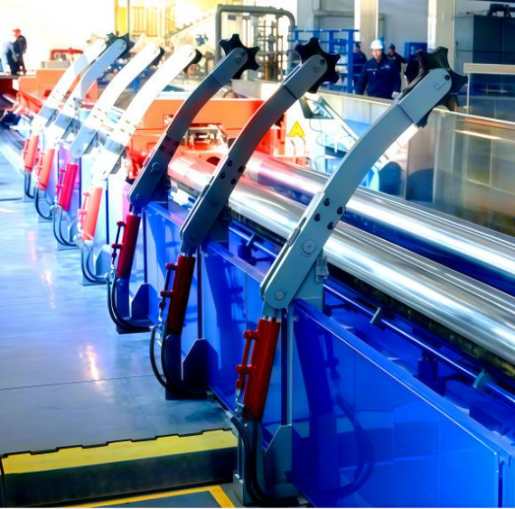
7 sets of clamping devices are installed on front brackets and middle portal frame, used for clamping the stator and housing of the motor.Dimension (L×W×H): 550×200×1700 mm; Single set weight: about 160 KG.(See Figure 10)
Figure 10 3D Drawing & Physical Photo of Clamping Device
3.2 Hydraulic Power System
The hydraulic power system (hydraulic station) is equipped with 1 set of circulating filtration and cooling device.
Rated pressure: 32 MPa; Rated flow: 200 L/min; Piston Pump: Displacement 100 L/min, rated pressure 32 MPa, 2 sets; Motor: 380V AC, power 2×55KW, 2 sets;Stainless Steel Oil Tank: Volume 1500 L.
Overall dimension (L×W×H): 1930×2000×2200 mm; Total weight: about 3.3 tons (excluding oil). It is placed at the tail of the main oil cylinder.(See Figure 11)
Figure 11 Hydraulic Station
3.3 Electric Control System
The electric control system is mainly composed of hydraulic station control cabinet, lamination equipment control cabinet, piano-type operation console, LED display screen and wireless remote controller.
3.3.1 Hydraulic Station Control Cabinet
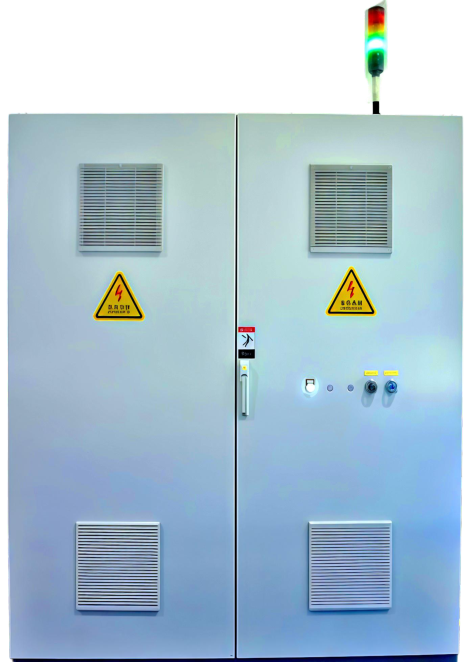
Core internal components include motor soft starter, AC circuit breaker, AC contactor, control relay, safety relay and other elements.(See Figure 12 for appearance)
3.3.2 Lamination Equipment Control Cabinet
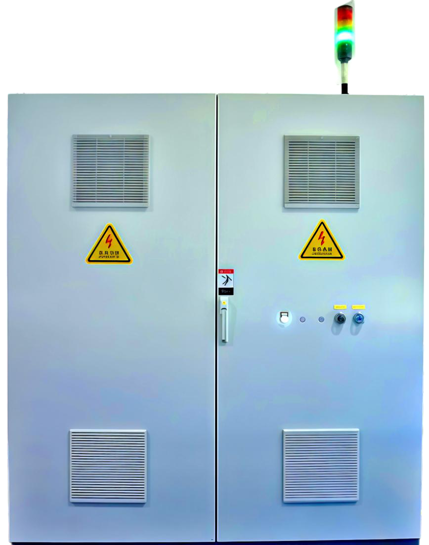
Core internal components include circuit protection elements, power supply unit, Programmable Logic Controller (PLC), EtherCAT coupler, PLC expansion module, servo motor driver, stepping motor driver, asynchronous motor inverter and intermediate relay. See Figure13 )
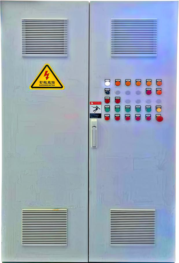
| Figure 12 Hydraulic Station Control Cabinet |
|
Figure 13 Lamination Equipment Control Cabinet |
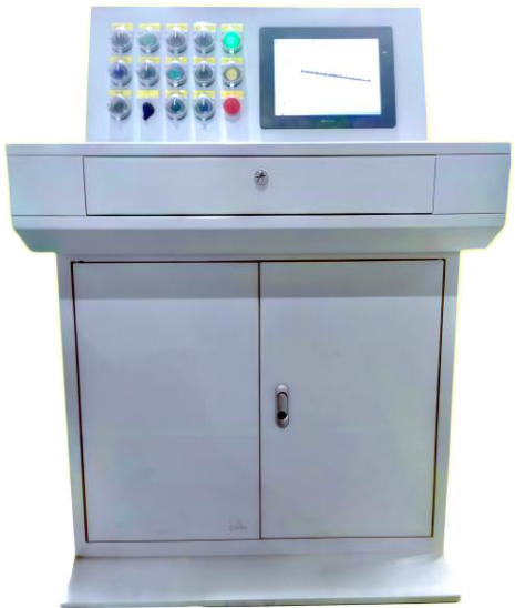
3.3.3 operator console
Equipped with industrial Ethernet switch, buttons, knobs and touch screen. (See Figure 14)
3.3.4 LED Display Screen
To facilitate on-site operators to grasp key control parameters in real time, a large LED screen is configured to display:Test piece No., outer barrel length, motor housing outer diameter, system oil pressure, system oil temperature, main cylinder pressure, laser distance measurement, trolley displacement, pressure head displacement.(See Figure 15)
For on-site operators to closely observe the workpiece and operate the equipment conveniently, the machine tool is equipped with a handheld wireless remote controller with emergency stop function. See Figure 16.
.png)
Figure 14 Piano-type Operation Console
.png)
Figure 15 Large LED Display Screen
.png)
Figure 16 Handheld Wireless Remote Controller





 EN
EN