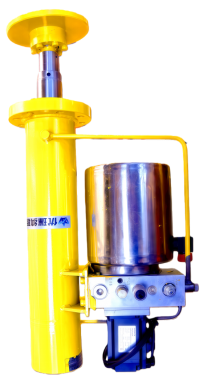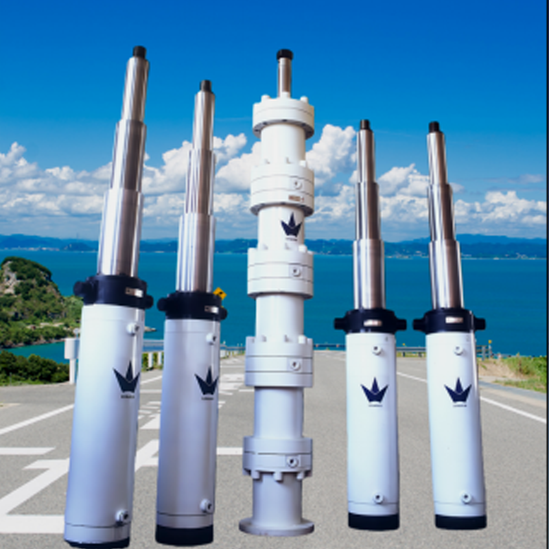
Photo of Electro-Hydraulic Cylinders
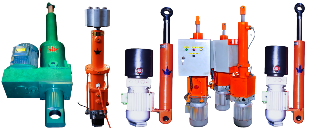
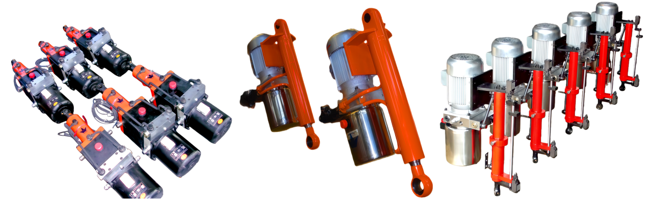
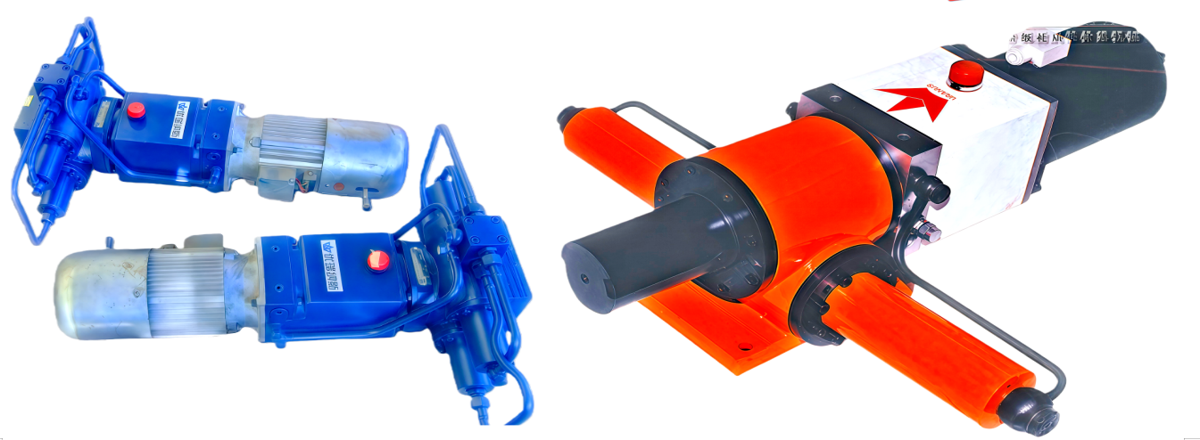
Overview of Electro-Hydraulic Cylinders (EHC)
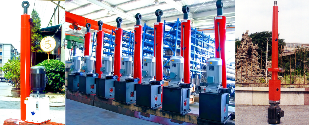
Electro-hydraulic cylinders (EHCs) are highly integrated hydraulic units that compactly combine motors, pumps, valves, cylinder bodies, and oil tanks. By switching the phase of a three-phase power supply, the extension and retraction of the hydraulic cylinder can be controlled. Compared to mechanically driven electric cylinders (e.g., ball screw or lead screw cylinders), EHCs offer the following advantages:
・Compact and lightweight: 30% smaller volume and 25% lighter weight than mechanical-driven electric cylinders at the same power output.
・Energy-efficient: 40% lower energy consumption, supporting load-starting and overload protection.・Intelligent adjustment: Thrust, speed, and stroke can be infinitely adjusted.
・High reliability: Built-in positioning lock mechanism, strong shock resistance, and smooth operation.
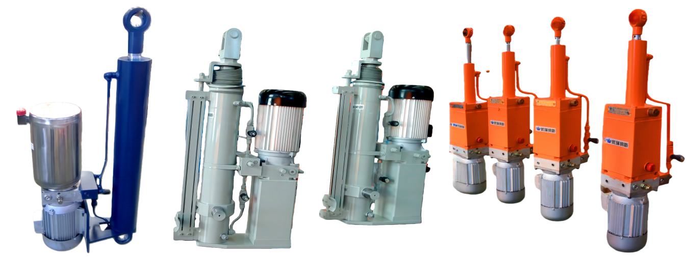
UE Series Technical Features
1. Core Architecture
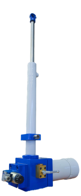
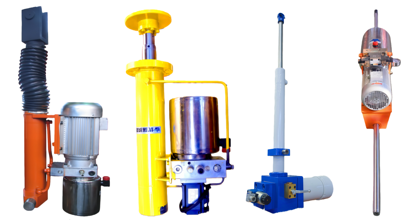
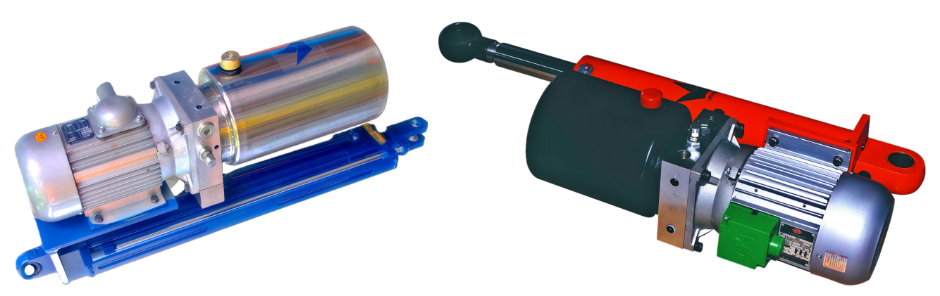
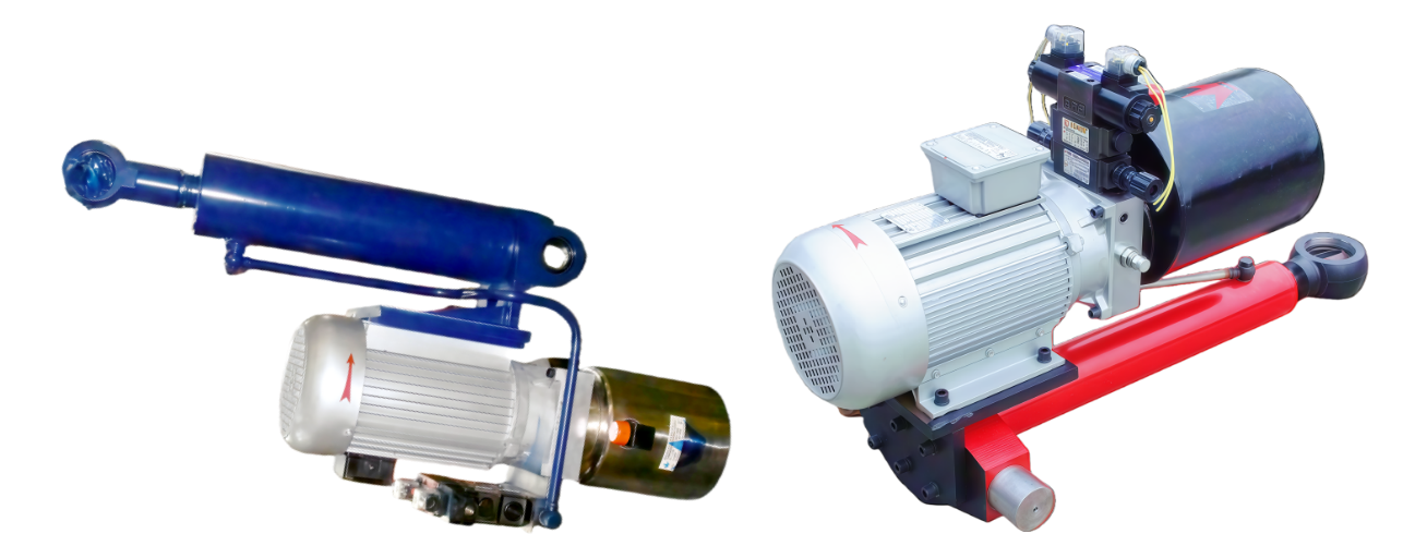
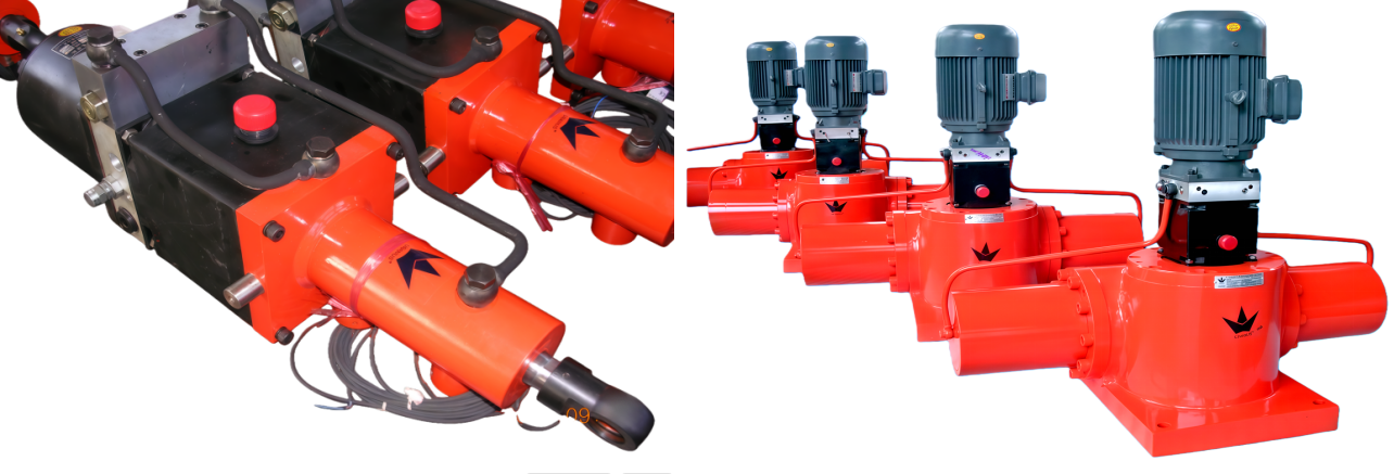
The UE series integrates a dedicated hydraulic power pack with the cylinder body, available in two configurations:
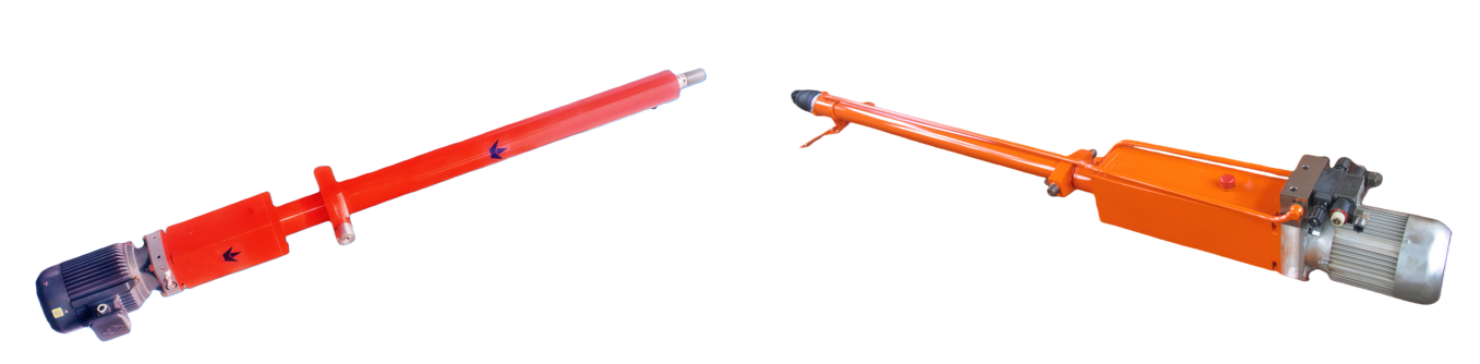
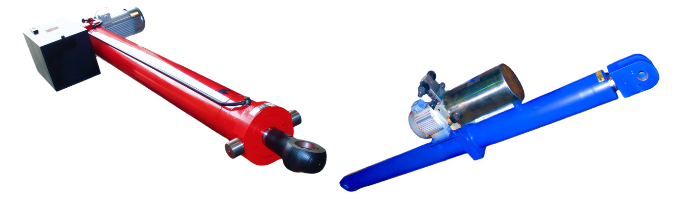
・UEC inline configuration: Power pack and cylinder aligned along a single axis, ideal for space-constrained applications.
・UEG parallel configuration: Power pack and cylinder arranged on parallel dual axes, enabling flexible installation.
2. Power System
・Power supply: Three-phase 380V/50Hz.
・Motor power:
・UEC series: 0.55kW–4kW (8 specifications).
・UEG series: 0.55kW–15kW (12 specifications)
・Hydraulic circuit: Equipped with high-quality pumps, valves, and seals. Components are precision-machined and rigorously tested per ISO standards.
3. Performance Parameters
Series |
Cylinder Diameter Range |
Max Thrust/Max Pull |
Mounting Options |
UEC |
7 types |
200kN/134kN |
3 rod diameters + 3 mounting styles |
UEG |
15 types |
1,227kN/920kN |
7 differential cylinders / 4 constant-speed cylinders |
4. Customization Services
Supports non-standard customization, including:
・Special functions (e.g., explosion-proof, high-temperature resistance).
・Higher thrust specifications.
・Compatibility with diverse hydraulic valve control systems.
Selection Guide for UE Series Electric Hydraulic Cylinders
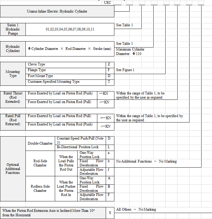
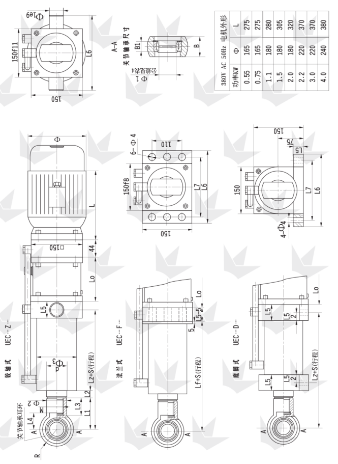
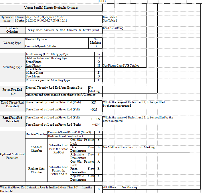
1. Structure: The UE series electric hydraulic cylinders (EHCs) consist of two main components: the hydraulic cylinder and the hydraulic power pack. In the UEC series, the hydraulic cylinder and power pack are assembled along a single axis, whereas in the UEG series, they are arranged in a parallel, dual-axis configuration. The hydraulic power pack comprises a motor, hydraulic pump, threaded cartridge valve, and oil tank. There are two series of hydraulic pumps, Series 1 and Series 2. Generally, Series 1 pumps are preferred for the UEC series, and Series 2 pumps for the UEG series.However, for special requirements, UEC cylinders can also use Series 2 pumps, and UEG cylinders can use Series 1 pumps.
2. Hydraulic Pumps: The Series 1 hydraulic pumps include 11 specifications, numbered 01–11. The Series 2 pumps include 10 specifications, numbered 20–29. Since fixed-displacement pumps are used, the push/pull speed of each cylinder-pump combination is constant and can be referenced in Tables 1 and 2.
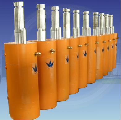
3. Hydraulic Cylinders: The UEC series offers 7 cylinder diameters, while the UEG series provides 15 cylinder diameters. Each cylinder diameter is available with three standard piston rod diameters, and non-standard piston rod diameters can also be custom-made according to requirements.
4. Selection Conditions: When selecting an electric hydraulic cylinder, you should first provide the following parameters and conditions as the basis for selection:
4.1 Push force, pull force, and stroke 4.2 Push speed and pull speed 4.3 Mounting type 4.4 Additional functional requirements
4.1 Push force, pull force, and stroke These parameters are determined by the working conditions. For example, when an EHC is used to horizontally push or pull a trolley or gate, the required push/pull force equals the sum of the resistance and acceleration forces of the trolley or gate. In this case, both push and pull forces are positive. When a hydraulic cylinder is used to lift and lower a heavy object, the push force is positive, and the pull force is negative. Conversely, if the cylinder lifts a heavy object and then lowers it, the pull force is positive, and the push force is negative. When the cylinder extends or retracts under no-load conditions, the push or pull force is zero. If the required push or pull force varies, the maximum value should be taken as the rated value.
If only one of the push or pull forces is positive, the cylinder diameter and rod diameter can be determined based on that value. For example, when a UEC EHC is required to lift a 5,000 kg object, referring to Table 1 for the maximum push force shows that cylinders with a diameter of Φ63 mm or larger are suitable. To reduce cost, Φ63 mm can be selected. Among the three piston rod diameters, thin rods are generally used for short strokes, and thick rods for long strokes. When a UEG EHC is used to lift a 5,000 kg object, referring to Table 2 for the maximum pull force allows the selection of either Φ63/32 or Φ63/36.
If both push and pull forces are positive, the largest cylinder diameter must be selected. For instance, if a UEC cylinder is required to provide a push force of 50 kN and a pull force of 60 kN, Table 1 shows that a Φ63 mm cylinder is needed for 50 kN push, and a Φ80 mm cylinder is needed for 60 kN pull. Therefore, the final selection should be a Φ80 mm cylinder.
The push and pull forces listed in Tables 1 and 2 are maximum allowable values. Within this range, you should determine the rated push and pull forces according to your requirements. Each EHC is strictly and accurately adjusted to the rated push/pull force before leaving the factory, and the relief valve is locked—please do not adjust it arbitrarily.
4.2 Push Speed and Pull Speed: After the cylinder diameter and piston rod diameter of the hydraulic cylinder are determined, the hydraulic pump is selected based on the required push and pull speeds. Push and pull speeds are determined by the stroke and cycle time. Push and pull speeds are determined by the stroke and cycle time. For example, consider a UEC cylinder with a push/pull force of 50 kN, a stroke of 500 mm, and a cylinder diameter of Φ80 mm:
A. If only the extension time is required as Tc=30s, the push speed is calculated as Vc=500÷30=16.7 mm/s. In this case, Pump No. 06 or 07 can be selected, and the rod diameter is optional. B. If only the retraction time is required as Th=30s, the pull speed is Vh=500÷30=16.7 mm/s. In this case, a piston rod diameter of Φ56 mm and Pump No. 03 should be selected. C. If the total push-pull cycle time is required to be 1 minute, a piston rod diameter of Φ56 mm and Pump No. 05 should be selected. Then, the push speed Vc=13 mm/s, extension time Tc=38.5 s; the pull speed Vh=26 mm/s, retraction time Th=19.2s; and the total push-pull cycle time is Tc+Th=57.7 s.
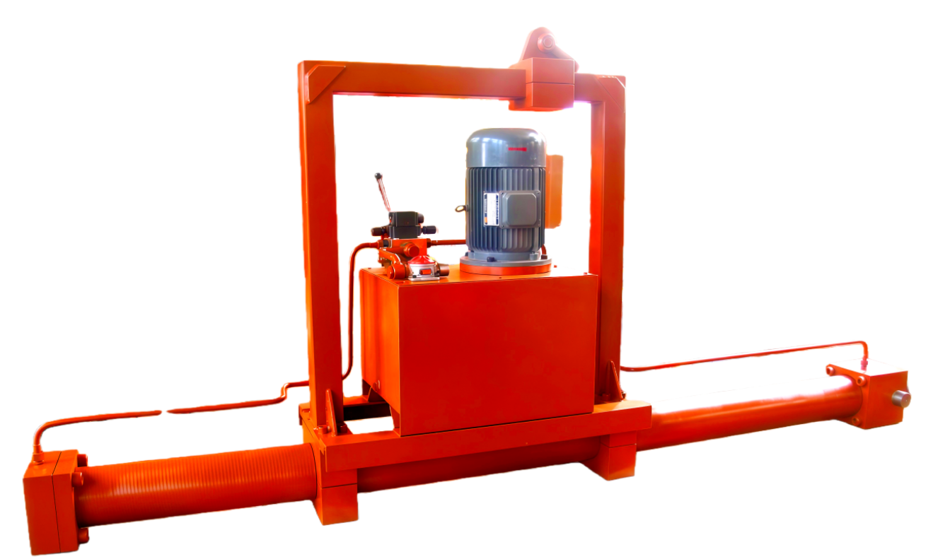
4.3 Mounting Types: The UEC series offers three standard mounting types, with diagrams and dimensions provided on pages 8 and 9. The UEG series provides ten mounting types, as shown on page 11. The UEG series assembles the hydraulic power pack with the company’s UG medium-to-high-pressure hydraulic cylinders for engineering and general machinery applications (see product catalog) in a parallel dual-axis configuration. The diagrams and dimensions of the hydraulic power pack are shown in Figure 2 and Table 4 on page 11. The diagrams and dimensions of the hydraulic cylinders are provided in the UG series cylinder catalog; except for the cylinder port, all mounting and connection dimensions remain identical to the catalog. Special mounting types and non-standard dimension EHCs requested by customers are designated with the letter T.
4.4 Optional Additional Functions
4.4.1 Constant-Speed Push/Pull Function: When equal push and pull speeds are required, the constant-speed function can be selected. Since this function is achieved through a differential hydraulic circuit, it can only provide approximately equal speeds. Moreover, for each cylinder diameter, only one specific piston rod diameter can achieve this function (see Table 3). For example, a Φ80/56‑500 UEC cylinder equipped with the constant-speed function, when using Pump No. 03, has a pull speed Vh=17 mm/s (see Table 1), giving a retraction time Th=29.4 s. The push speed is calculated as Vc=Vh÷ψ=17÷0.96=17.7 mm/s (see Table 3), resulting in an extension time Tc=500÷Vc≈28.2 s. The total push-pull cycle time is Th+Tc=57.6s. The maximum pull force is Fh=53 kN, and the maximum push force is Fc=ψFh=0.96×53=50.88 kN.
For UEG series constant-speed cylinders (see Figure 2), since the effective areas of the two cylinder chambers are equal, the reciprocating speeds are inherently equal. In addition, the constant-speed function can be achieved with all available piston rod diameters in this series.
4.4.2 Bi-Directional Position Lock. This function is achieved by adding pilot-operated check valves to the return lines of both chambers of the hydraulic cylinder within the system circuit. As a result, when the electric hydraulic cylinder stops operating, the piston will remain stationary at any position and will not move under external forces. Since the company’s EHCs use high-quality imported seals and valves, combined with precision manufacturing processes, the hydraulic cylinder and valves are guaranteed to be leak-free. Even under prolonged external forces or impacts, there will be no leakage or unintended movement.
4.4.3 Rod-Side Chamber One-Way Position Lock: A pilot-operated check valve is installed only in the rod-side chamber return line. This function is generally used when the piston rod end is required to suspend a heavy load for a long period or under similar conditions where the piston rod is subjected to external pulling forces.
4.4.4 Rod-Side Chamber Fixed or Adjustable Flow Deceleration. When it is necessary to lower a lifted heavy load slowly, a throttle valve is installed in the rod-side chamber return line to reduce the descending speed caused by gravity. A fixed throttle uses a check plate with a small orifice. Its advantage is low cost, while its disadvantage is that the descending speed cannot be adjusted. This is commonly used in mass-produced products. An adjustable flow uses a pilot-operated adjustable flow screw-in cartridge valve, allowing the user to freely set the descending speed. , allowing the user to freely set the descending speed. For special operating conditions, products with a constant-speed down valve or a downward balancing valve can also be provided.
4.4.5 Rodless-Side Chamber One-Way Position Lock. A pilot-operated check valve is installed only in the rodless-side chamber return line. This function is generally used when the piston rod is required to support a heavy load for a long period or under similar conditions where the piston rod is subjected to external pushing forces.
4.4.6 Rodless-Side Chamber Fixed or Adjustable Flow Deceleration. When the piston rod lowers a lifted heavy load slowly, a fixed or adjustable flow valve should be installed in the rodless-side chamber to reduce the descending speed. For this type of application, it is recommended to use the company’s electro-hydraulic plunger cylinders, which can reduce cost, simplify operation control, and save energy.
Electric hydraulic cylinders equipped with flow control check valves in both chambers can achieve stepless speed regulation. However, since throttling generates heat and the cylinder’s oil tank is relatively small, this configuration is not suitable for applications requiring frequent directional changes or continuous operation.
5. The company can also provide electric hydraulic cylinders with the following special functions.
5.1 Electric hydraulic cylinders with terminal position proximity switches. These cylinders not only send an electrical signal when the piston reaches the end of its stroke, but can also automatically reverse direction.
5.2 Electric hydraulic cylinders with external travel switches. These allow stepless adjustment of the cylinder stroke and reversal at any desired stroke position.
5.3 Electric hydraulic cylinders with automatic pressure-operated directional valves. The cylinder automatically reverses direction when it reaches the end of its stroke or encounters an overload condition during operation.
5.4 Servo electric hydraulic cylinders with external or internal displacement sensors. These cylinders can accurately display and record the cylinder stroke (maximum precision 2 μm), and allow variable-speed motion, oscillation, dwell, and random operation at any position.
5.5 Electric hydraulic cylinders can be configured with the company’s UP series hydraulic power packs and UG series hydraulic cylinders to provide a wide variety of functional options. For details, please refer to the company’s hydraulic power pack catalog.
6. Motor: The UE series electric hydraulic cylinders use a 380 V, 50 Hz three-phase asynchronous motor.
The required motor power NNN is determined by the following calculation:
Nc=1.3FcVc Nh=1.3FhVh The larger of Nc and Nh is taken as the required motor power N, and it must not exceed the motor’s rated power.
Nc is the hydraulic cylinder extension power, and Nh is the hydraulic cylinder retraction power, both in watts (W).
Fc is the cylinder push force, and Fh is the cylinder pull force, both in kilonewtons (kN).
Vc is the cylinder push speed, and Vh is the cylinder pull speed, both in millimeters per second (mm/s).
7. Installation Position: When the operating position of the electric hydraulic cylinder is with the piston rod end vertical or inclined upwards (more than 10° from the horizontal), it should be marked as S. In this case, the cylinder requires modification of the oil tank filler port and the internal suction tube position.
8. Selection Recommendations: The cost of a UE series electric hydraulic cylinder is proportional to its push and pull forces, stroke, speed, and the number of additional functions. To save costs, please select the most appropriate model whenever possible. If any details in our selection guide are unclear, or if you have special requirements, please contact us. We will be pleased to assist you in selecting, designing, and manufacturing the electric hydraulic cylinder that best suits your application.
9. Operating and Maintenance Precautions for Electric Hydraulic Cylinders:
9.1 Do not place or operate the electric hydraulic cylinder in conditions of direct water exposure, excessive humidity, high temperature, low temperature, or other adverse environments.
9.2 At the factory, the cylinder’s oil port is sealed with an O-ring to block the breather. During use, this O-ring should be removed to allow the oil tank to breathe. For constant-speed circuits and constant-speed cylinders, the O-ring may remain in place.
9.3 The recommended working fluid is anti-wear hydraulic oil with a viscosity of 25~40cts (generally #46), turbine oil, or mineral-based lubricating oils. The fluid must be filtered, with a cleanliness level of NAS 1638 grade 9 or ISO 4406 19/15 or better. The operating temperature should be maintained between 15~60 °C.
9.4 During the first use, ensure that all air is purged from the hydraulic cylinder. When retracting the piston rod, both the rod-side chamber and the oil tank must be completely filled with working fluid. Since the cylinder’s oil tank is small, any external leakage must be repaired immediately and the fluid level restored. Insufficient working fluid can cause pump cavitation, leading to rapid pump damage and cylinder cavitation. If crawling or vibration occurs during operation, first check for low fluid level, pump cavitation, or air in the hydraulic cylinder.
9.5 The relief valve is factory-set and should not be arbitrarily adjusted. Overloading can damage the pump, motor, and other components.
9.6 Due to the small size of the oil tank, these cylinders are not suitable for continuous long-duration operation or frequent directional changes. If high oil temperature occurs during continuous operation, allow the system to cool before resuming use. For cylinders requiring continuous long-duration operation or frequent reversal, this must be specified when ordering so that design measures can be taken to prevent excessive or rapid temperature rise.
9.7 The working fluid should be replaced once a year.
Technical Specifications Table for Series 1 Hydraulic Pumps of UE Series Electric Hydraulic Cylinders
table 1
|
Series 1 Hydraulic Pumps
Hydraulic Cylinders
|
01 |
02 |
03 |
Cylinder diameter |
40mm |
20mm/s (push speed) |
26KN (maximum push force) |
27mm/s (push speed) |
26KN (maximum push force) |
36mm/s (push speed) |
|
Rod diameter |
20 mm |
27mm/s (pull speed) |
19KN (maximum pull force) |
36mm/s (pull speed) |
19KN (maximum pull force) |
47mm/s (pull speed) |
|
22mm |
29mm/s (pull speed) |
18KN (maximum pull force) |
38mm/s (pull speed) |
18KN (maximum pull force) |
51mm/s (pull speed) |
|
28mm |
39mm/s (pull speed) |
13KN (maximum pull force) |
52mm/s (pull speed) |
13KN (maximum pull force) |
70mm/s (pull speed) |
|
Table 1: For ease of reference, the units of the values in Tables 1 and 2 are omitted.
Note: The UEC series in-line electric hydraulic cylinders preferentially use this series.
|
Series 1 Hydraulic Pumps
Hydraulic Cylinders
|
01 |
02 |
03 |
04 |
05 |
06 |
07 |
08 |
09 |
10 |
11 |
Cylinder diameter |
40 |
20 |
26 |
27 |
26 |
36 |
26 |
44 |
26 |
53 |
25 |
62 |
25 |
71 |
22 |
84 |
22 |
100 |
21 |
129 |
20 |
169 |
18 |
Rod diameter |
20 |
27 |
19 |
36 |
19 |
47 |
19 |
59 |
19 |
71 |
18 |
83 |
18 |
95 |
17 |
113 |
17 |
133 |
16 |
172 |
15 |
225 |
14 |
22 |
29 |
18 |
38 |
18 |
51 |
18 |
64 |
18 |
76 |
17 |
89 |
17 |
102 |
15 |
121 |
15 |
143 |
15 |
185 |
14 |
242 |
13 |
28 |
39 |
13 |
52 |
13 |
70 |
13 |
87 |
13 |
105 |
13 |
122 |
13 |
139 |
11 |
165 |
11 |
196 |
10 |
253 |
10 |
331 |
9 |
Cylinder diameter |
50 |
13 |
41 |
17 |
41 |
23 |
41 |
28 |
41 |
34 |
39 |
40 |
39 |
45 |
35 |
54 |
35 |
64 |
33 |
82 |
31 |
108 |
28 |
Rod diameter |
25 |
17 |
31 |
23 |
31 |
30 |
31 |
40 |
31 |
45 |
29 |
53 |
29 |
61 |
26 |
72 |
26 |
85 |
25 |
110 |
23 |
144 |
22 |
28 |
19 |
28 |
25 |
28 |
33 |
28 |
41 |
28 |
50 |
27 |
58 |
27 |
66 |
24 |
79 |
24 |
93 |
23 |
120 |
21 |
157 |
20 |
36 |
27 |
20 |
35 |
20 |
47 |
20 |
59 |
20 |
71 |
19 |
83 |
19 |
94 |
17 |
112 |
17 |
133 |
16 |
171 |
15 |
224 |
14 |
Cylinder diameter |
63 |
8.1 |
65 |
11 |
65 |
14 |
65 |
18 |
65 |
21 |
62 |
25 |
62 |
29 |
56 |
34 |
56 |
40 |
53 |
52 |
50 |
68 |
44 |
Rod diameter |
32 |
11 |
48 |
14 |
48 |
19 |
48 |
24 |
48 |
29 |
46 |
34 |
46 |
39 |
41 |
46 |
41 |
54 |
39 |
70 |
37 |
92 |
34 |
36 |
12 |
44 |
16 |
44 |
21 |
44 |
27 |
44 |
32 |
42 |
37 |
42 |
43 |
37 |
51 |
37 |
60 |
35 |
77 |
33 |
101 |
31 |
45 |
16 |
32 |
22 |
32 |
29 |
32 |
37 |
32 |
44 |
30 |
51 |
30 |
58 |
27 |
69 |
27 |
82 |
26 |
106 |
24 |
139 |
22 |
Cylinder diameter |
80 |
5 |
105 |
6.7 |
105 |
8.9 |
105 |
11 |
105 |
13 |
100 |
16 |
100 |
18 |
90 |
21 |
90 |
25 |
85 |
32 |
80 |
42 |
75 |
Rod diameter |
40 |
6.7 |
79 |
8.9 |
79 |
12 |
79 |
15 |
79 |
18 |
75 |
21 |
75 |
24 |
67 |
28 |
67 |
33 |
64 |
43 |
60 |
56 |
56 |
45 |
7.3 |
72 |
9.7 |
72 |
13 |
72 |
16 |
72 |
19 |
68 |
23 |
68 |
26 |
61 |
31 |
61 |
37 |
58 |
47 |
55 |
62 |
51 |
56 |
9.8 |
53 |
13 |
53 |
17 |
53 |
22 |
53 |
26 |
51 |
30 |
51 |
35 |
46 |
41 |
46 |
49 |
43 |
63 |
41 |
83 |
38 |
Cylinder diameter |
90 |
3.9 |
133 |
5.3 |
133 |
7 |
133 |
8.8 |
133 |
11 |
127 |
12 |
127 |
14 |
114 |
17 |
114 |
20 |
108 |
25 |
101 |
33 |
95 |
Rod diameter |
45 |
5.3 |
100 |
7 |
100 |
9.4 |
100 |
12 |
100 |
14 |
95 |
16 |
95 |
19 |
85 |
22 |
85 |
26 |
81 |
34 |
76 |
44 |
71 |
50 |
5.7 |
92 |
7.6 |
92 |
10 |
92 |
13 |
92 |
15 |
88 |
18 |
88 |
20 |
79 |
24 |
79 |
29 |
74 |
37 |
70 |
48 |
65 |
63 |
7.7 |
68 |
10 |
68 |
14 |
68 |
17 |
68 |
21 |
64 |
24 |
64 |
28 |
58 |
33 |
58 |
39 |
55 |
50 |
51 |
65 |
48 |
Cylinder diameter |
100 |
3.2 |
165 |
4.3 |
165 |
5.7 |
165 |
7.1 |
165 |
8.5 |
157 |
9.9 |
157 |
11 |
141 |
14 |
141 |
16 |
133 |
21 |
125 |
27 |
117 |
Rod diameter |
50 |
4.3 |
123 |
5.7 |
123 |
7.6 |
123 |
9.5 |
123 |
11 |
117 |
13 |
117 |
15 |
106 |
18 |
106 |
21 |
100 |
27 |
94 |
36 |
88 |
56 |
4.7 |
113 |
6.2 |
113 |
8.3 |
113 |
10 |
113 |
12 |
107 |
14 |
107 |
17 |
97 |
20 |
97 |
23 |
91 |
30 |
86 |
39 |
80 |
70 |
6.3 |
84 |
8.4 |
84 |
11 |
84 |
14 |
84 |
17 |
80 |
20 |
80 |
22 |
72 |
26 |
72 |
31 |
68 |
40 |
64 |
53 |
60 |
Cylinder diameter |
110 |
2.6 |
200 |
3.5 |
200 |
4.7 |
200 |
5.9 |
200 |
7 |
190 |
8.2 |
190 |
9.4 |
171 |
11 |
171 |
13 |
161 |
17 |
152 |
22 |
142 |
Rod diameter |
56 |
3.6 |
148 |
4.8 |
148 |
6.3 |
148 |
7.9 |
148 |
9.5 |
140 |
11 |
140 |
13 |
126 |
15 |
126 |
18 |
119 |
23 |
112 |
30 |
105 |
63 |
3.9 |
134 |
5.2 |
134 |
7 |
134 |
8.7 |
134 |
10 |
127 |
12 |
127 |
14 |
115 |
17 |
115 |
20 |
108 |
25 |
102 |
33 |
95 |
80 |
5.6 |
94 |
7.5 |
94 |
10 |
94 |
12 |
94 |
15 |
89 |
17 |
89 |
20 |
80 |
24 |
80 |
28 |
76 |
36 |
71 |
47 |
67 |
Technical Specifications Table for Series 2 Hydraulic Pumps of UE Series Electric Hydraulic Cylinders
table 2
|
Series 2 Hydraulic Pumps
Hydraulic Cylinders
|
20 |
21 |
22 |
23 |
24 |
25 |
26 |
27 |
28 |
29 |
Cylinder diameter |
40 |
55 |
31 |
79 |
31 |
111 |
31 |
140 |
31 |
196 |
31 |
236 |
31 |
284 |
31 |
331 |
27 |
391 |
25 |
440 |
22 |
Rod diameter |
20 |
73 |
23 |
105 |
23 |
148 |
23 |
187 |
23 |
262 |
23 |
314 |
23 |
378 |
23 |
442 |
20 |
522 |
18 |
588 |
17 |
22 |
78 |
22 |
113 |
22 |
159 |
22 |
201 |
22 |
282 |
22 |
338 |
22 |
407 |
22 |
475 |
19 |
561 |
17 |
632 |
15 |
28 |
107 |
16 |
154 |
16 |
218 |
16 |
275 |
16 |
385 |
16 |
462 |
16 |
556 |
16 |
650 |
14 |
767 |
12 |
864 |
11 |
Cylinder diameter |
50 |
35 |
49 |
50 |
49 |
71 |
49 |
90 |
49 |
126 |
49 |
151 |
49 |
181 |
49 |
212 |
43 |
250 |
39 |
282 |
35 |
Rod diameter |
25 |
47 |
36 |
67 |
36 |
95 |
36 |
120 |
36 |
168 |
36 |
201 |
36 |
242 |
36 |
283 |
32 |
334 |
29 |
376 |
26 |
28 |
51 |
33 |
73 |
33 |
104 |
33 |
131 |
33 |
183 |
33 |
220 |
33 |
264 |
33 |
309 |
29 |
365 |
27 |
411 |
24 |
36 |
73 |
23 |
104 |
23 |
148 |
23 |
186 |
23 |
261 |
23 |
313 |
23 |
377 |
23 |
440 |
20 |
520 |
18 |
586 |
17 |
Cylinder diameter |
63 |
22 |
78 |
32 |
78 |
45 |
78 |
56 |
78 |
79 |
78 |
95 |
78 |
114 |
78 |
134 |
68 |
158 |
62 |
178 |
56 |
Rod diameter |
32 |
30 |
57 |
43 |
57 |
60 |
57 |
76 |
57 |
107 |
57 |
128 |
57 |
154 |
57 |
180 |
50 |
213 |
46 |
239 |
41 |
36 |
33 |
52 |
47 |
52 |
66 |
52 |
84 |
52 |
118 |
52 |
141 |
52 |
170 |
52 |
198 |
46 |
234 |
42 |
264 |
37 |
45 |
45 |
38 |
65 |
38 |
91 |
38 |
115 |
38 |
162 |
38 |
194 |
38 |
233 |
38 |
273 |
33 |
322 |
30 |
363 |
27 |
Cylinder diameter |
80 |
14 |
125 |
20 |
125 |
28 |
125 |
35 |
125 |
49 |
125 |
59 |
125 |
71 |
125 |
83 |
110 |
98 |
100 |
110 |
90 |
Rod diameter |
40 |
18 |
94 |
26 |
94 |
37 |
94 |
47 |
94 |
65 |
94 |
79 |
94 |
95 |
94 |
110 |
83 |
130 |
75 |
147 |
67 |
45 |
20 |
86 |
29 |
86 |
41 |
86 |
51 |
86 |
72 |
86 |
86 |
86 |
104 |
86 |
121 |
75 |
143 |
68 |
161 |
61 |
56 |
27 |
64 |
39 |
64 |
54 |
64 |
69 |
64 |
96 |
64 |
116 |
64 |
139 |
64 |
162 |
56 |
192 |
51 |
216 |
46 |
Cylinder diameter |
90 |
11 |
159 |
16 |
159 |
22 |
159 |
28 |
159 |
39 |
159 |
47 |
159 |
56 |
159 |
65 |
140 |
77 |
127 |
87 |
114 |
Rod diameter |
45 |
14 |
119 |
21 |
119 |
29 |
119 |
37 |
119 |
52 |
119 |
62 |
119 |
75 |
119 |
87 |
105 |
103 |
95 |
116 |
85 |
50 |
16 |
110 |
22 |
110 |
32 |
110 |
40 |
110 |
56 |
110 |
67 |
110 |
81 |
110 |
95 |
96 |
112 |
88 |
126 |
79 |
63 |
21 |
81 |
30 |
81 |
43 |
81 |
54 |
81 |
76 |
81 |
91 |
81 |
110 |
81 |
128 |
71 |
152 |
64 |
171 |
58 |
Cylinder diameter |
100 |
8.7 |
196 |
13 |
196 |
18 |
196 |
22 |
196 |
31 |
196 |
38 |
196 |
45 |
196 |
53 |
172 |
63 |
157 |
71 |
141 |
Rod diameter |
50 |
12 |
147 |
17 |
147 |
24 |
147 |
30 |
147 |
42 |
147 |
50 |
147 |
60 |
147 |
71 |
129 |
83 |
117 |
94 |
106 |
56 |
13 |
134 |
18 |
134 |
26 |
124 |
33 |
134 |
46 |
134 |
55 |
134 |
66 |
134 |
77 |
118 |
91 |
107 |
103 |
97 |
70 |
17 |
100 |
25 |
100 |
35 |
100 |
44 |
100 |
62 |
100 |
74 |
100 |
89 |
100 |
104 |
88 |
123 |
80 |
138 |
72 |
Cylinder diameter |
110 |
7.2 |
237 |
10 |
237 |
15 |
237 |
19 |
237 |
26 |
237 |
31 |
237 |
37 |
237 |
44 |
209 |
52 |
190 |
58 |
171 |
Rod diameter |
56 |
9.8 |
176 |
14 |
176 |
20 |
176 |
25 |
176 |
35 |
176 |
42 |
176 |
51 |
176 |
59 |
154 |
70 |
140 |
79 |
126 |
63 |
11 |
159 |
15 |
159 |
22 |
159 |
28 |
159 |
39 |
159 |
46 |
159 |
56 |
159 |
65 |
140 |
78 |
127 |
87 |
115 |
80 |
15 |
112 |
22 |
112 |
31 |
112 |
39 |
112 |
55 |
112 |
66 |
112 |
81 |
112 |
93 |
98 |
110 |
89 |
124 |
80 |
Cylinder diameter |
125 |
5.6 |
306 |
8 |
306 |
11 |
306 |
14 |
306 |
20 |
306 |
24 |
306 |
29 |
306 |
34 |
270 |
40 |
245 |
45 |
220 |
Rod diameter |
63 |
7.5 |
228 |
11 |
228 |
15 |
228 |
19 |
228 |
27 |
228 |
32 |
228 |
39 |
228 |
45 |
201 |
54 |
183 |
60 |
164 |
70 |
8.2 |
210 |
12 |
210 |
17 |
210 |
21 |
210 |
29 |
210 |
35 |
210 |
42 |
210 |
49 |
185 |
58 |
168 |
66 |
151 |
90 |
12 |
147 |
17 |
147 |
24 |
147 |
30 |
147 |
42 |
147 |
50 |
147 |
60 |
147 |
70 |
130 |
83 |
118 |
94 |
106 |
Technical Specifications Table for Series 2 Hydraulic Pumps of UE Series Electric Hydraulic Cylinders
Table 2(Cont'd)
|
Series 2 Hydraulic Pumps
Hydraulic Cylinders
|
20 |
21 |
22 |
23 |
24 |
25 |
26 |
27 |
28 |
29 |
Cylinder diameter |
140 |
4.5 |
384 |
6.4 |
384 |
9.1 |
384 |
11 |
384 |
16 |
384 |
19 |
384 |
23 |
384 |
27 |
338 |
32 |
307 |
36 |
277 |
Rod diameter |
70 |
6 |
288 |
8.6 |
288 |
12 |
288 |
15 |
288 |
21 |
288 |
26 |
288 |
31 |
288 |
36 |
254 |
43 |
231 |
48 |
207 |
80 |
6.6 |
259 |
9.5 |
259 |
13 |
259 |
17 |
259 |
24 |
259 |
29 |
259 |
34 |
259 |
40 |
228 |
47 |
207 |
53 |
186 |
100 |
9.1 |
188 |
13 |
188 |
19 |
188 |
23 |
188 |
33 |
188 |
39 |
188 |
47 |
188 |
55 |
165 |
65 |
150 |
73 |
135 |
Cylinder diameter |
150 |
3.9 |
441 |
5.6 |
441 |
7.9 |
441 |
10 |
441 |
14 |
441 |
17 |
441 |
20 |
441 |
24 |
388 |
28 |
353 |
31 |
318 |
Rod diameter |
75 |
5.2 |
331 |
7.5 |
331 |
11 |
331 |
13 |
331 |
19 |
331 |
22 |
331 |
27 |
331 |
31 |
291 |
37 |
265 |
42 |
238 |
85 |
5.7 |
300 |
8.2 |
300 |
12 |
300 |
15 |
300 |
21 |
300 |
25 |
300 |
30 |
300 |
35 |
264 |
41 |
240 |
46 |
216 |
105 |
7.6 |
225 |
11 |
225 |
15 |
225 |
20 |
225 |
27 |
225 |
33 |
225 |
40 |
225 |
46 |
198 |
55 |
180 |
61 |
162 |
Cylinder diameter |
160 |
3.4 |
502 |
4.9 |
502 |
6.9 |
502 |
8.8 |
502 |
12 |
502 |
15 |
502 |
18 |
502 |
21 |
442 |
24 |
402 |
28 |
362 |
Rod diameter |
80 |
4.6 |
377 |
6.5 |
377 |
9.3 |
377 |
12 |
377 |
16 |
377 |
20 |
377 |
24 |
377 |
28 |
331 |
33 |
301 |
37 |
271 |
90 |
5 |
343 |
7.2 |
343 |
10 |
343 |
13 |
343 |
18 |
343 |
22 |
343 |
26 |
343 |
30 |
302 |
36 |
274 |
40 |
247 |
110 |
6.5 |
265 |
9.3 |
265 |
13 |
265 |
17 |
265 |
23 |
265 |
28 |
265 |
34 |
265 |
39 |
233 |
46 |
212 |
52 |
190 |
Cylinder diameter |
180 |
2.7 |
636 |
3.9 |
636 |
5.5 |
636 |
6.9 |
636 |
9.7 |
636 |
12 |
636 |
14 |
636 |
16 |
560 |
19 |
509 |
22 |
458 |
Rod diameter |
90 |
3.6 |
477 |
5.2 |
477 |
7.3 |
477 |
9.2 |
477 |
13 |
477 |
16 |
477 |
19 |
477 |
22 |
419 |
26 |
381 |
29 |
343 |
100 |
3.9 |
439 |
5.6 |
439 |
7.9 |
439 |
10 |
439 |
14 |
439 |
17 |
439 |
20 |
439 |
24 |
387 |
28 |
351 |
31 |
316 |
125 |
5.2 |
329 |
7.5 |
329 |
11 |
329 |
13 |
329 |
19 |
329 |
22 |
329 |
27 |
329 |
32 |
289 |
37 |
263 |
42 |
237 |
Cylinder diameter |
200 |
2.2 |
785 |
3.1 |
785 |
4.4 |
785 |
5.6 |
785 |
7.9 |
785 |
9.4 |
785 |
11 |
785 |
13 |
691 |
16 |
628 |
18 |
565 |
Rod diameter |
100 |
2.9 |
589 |
4.2 |
589 |
5.9 |
589 |
7.5 |
589 |
10 |
589 |
13 |
589 |
15 |
589 |
18 |
518 |
21 |
471 |
24 |
424 |
110 |
3.1 |
547 |
4.5 |
547 |
6.4 |
547 |
8 |
547 |
11 |
547 |
14 |
547 |
16 |
547 |
19 |
482 |
22 |
438 |
25 |
394 |
140 |
4.3 |
400 |
6.2 |
400 |
8.7 |
400 |
11 |
400 |
15 |
400 |
18 |
400 |
22 |
400 |
26 |
352 |
31 |
320 |
35 |
288 |
Cylinder diameter |
220 |
1.8 |
950 |
2.6 |
950 |
3.7 |
950 |
4.6 |
950 |
6.5 |
950 |
7.8 |
950 |
9.4 |
950 |
11 |
836 |
13 |
760 |
15 |
684 |
Rod diameter |
110 |
2.4 |
712 |
3.5 |
712 |
4.9 |
712 |
6.2 |
712 |
8.7 |
712 |
10 |
712 |
12 |
712 |
15 |
627 |
17 |
570 |
19 |
513 |
125 |
2.7 |
643 |
3.8 |
643 |
5.4 |
643 |
6.8 |
643 |
9.6 |
643 |
12 |
643 |
14 |
643 |
16 |
566 |
19 |
514 |
22 |
463 |
160 |
3.8 |
447 |
5.5 |
447 |
7.8 |
447 |
9.8 |
447 |
14 |
447 |
17 |
447 |
20 |
447 |
23 |
394 |
27 |
358 |
31 |
322 |
Cylinder diameter |
250 |
1.4 |
1227 |
2 |
1227 |
2.8 |
1227 |
3.6 |
1227 |
5 |
1227 |
6 |
1227 |
7.3 |
1227 |
8.5 |
1080 |
10 |
981 |
11 |
883 |
Rod diameter |
125 |
1.9 |
920 |
2.7 |
920 |
3.8 |
920 |
4.8 |
920 |
6.7 |
920 |
8 |
920 |
9.7 |
920 |
11 |
810 |
13 |
736 |
15 |
662 |
140 |
2 |
842 |
2.9 |
842 |
4.1 |
842 |
5.2 |
842 |
7.3 |
842 |
8.8 |
842 |
11 |
842 |
12 |
741 |
15 |
673 |
16 |
606 |
180 |
2.9 |
591 |
4.2 |
591 |
5.9 |
591 |
7.4 |
591 |
10 |
591 |
13 |
591 |
15 |
590 |
18 |
520 |
21 |
472 |
23 |
425 |
Technical Specifications Table for UE Series Electric Hydraulic Cylinders with Constant-Speed Differential Circuit
Table 3
Cylinder diameter mm |
40 |
50 |
63 |
80 |
90 |
100 |
110 |
125 |
140 |
150 |
180 |
200 |
220 |
250 |
Rod diameter mm |
28 |
36 |
45 |
56 |
63 |
70 |
80 |
90 |
100 |
105 |
125 |
140 |
160 |
180 |
Speed Ratio (ψ) |
0.96 |
1.08 |
1.04 |
0.96 |
0.96 |
0.96 |
1.12 |
1.08 |
1.04 |
0.96 |
0.93 |
0.96 |
1.12 |
1.08 |
Calculation Formula |
|
Vc Push Speed, Vh Pull Speed, Unit: mm/s |
ψ-Speed Ratio |
Fc max – Maximum Push Force, Fh max – Maximum Pull Force, Unit: kN |
Vh and Fh max — Refer to Table 1 or Table 2 |
UEC Series Inline Electro-Hydraulic Cylinder Selection Method
Note 1: When the piston rod is extended, external pulling forces on the piston rod are marked as negative. For example, if the piston rod is pointing downward and a 1,000 kg load is being lowered slowly from the rod end, the pulling force exerted by the load on the piston rod is 10 kN, and it should be marked as –10 kN.
Note 2: When the piston rod is retracted, external pushing forces on the piston rod are marked as negative. For example, if the extended piston rod is pointing upward, supporting a 1,000 kg load that is being lowered slowly, the pushing force exerted by the load on the piston rod is 10 kN, and it should be marked as -10 kN.
Note 3: The constant-speed push/pull function is achieved using a differential circuit. Both the push/pull speed and the maximum push/pull force are approximate; please refer to Table 3.
Cylinder diameter |
Rod diameter |
M |
Φ2 |
R |
B |
B1 |
Φ1 |
Φ3 |
Φ4 |
L1 |
L2 |
L3 |
L4 |
L5 |
L6 |
L7 |
Lz |
Lf |
LO≥150 |
Dimensions |
Bearing Tolerances |
40 |
20 |
M14*1.5 |
25 |
25 |
16 |
20 |
0-0.01 |
58 |
13 |
50 |
16 |
25 |
30 |
25 |
200 |
175 |
220 |
212 |
0.04S |
22 |
M16*1.5 |
28 |
0.05S |
28 |
M22*1.5 |
35 |
M22*1.5 |
50 |
25 |
M20*1.5 |
28 |
35 |
22 |
30 |
70 |
13 |
60 |
18 |
30 |
40 |
30 |
200 |
175 |
233 |
223 |
0.06S |
28 |
M22*1.5 |
35 |
M22*1.5 |
36 |
M27*2 |
42 |
0.12S |
63 |
32 |
M24*1.5 |
35 |
83 |
17 |
65 |
20 |
35 |
40 |
30 |
200 |
175 |
270 |
260 |
0.10S |
36 |
M27*2 |
42 |
0.12S |
45 |
M33*2 |
45 |
0.20S |
80 |
40 |
M30*2 |
42 |
45 |
28 |
40 |
0-0.012 |
108 |
17 |
105 |
20 |
45 |
55 |
40 |
200 |
175 |
223 |
307 |
0.16S |
45 |
M33*2 |
48 |
0.20S |
56 |
M42*3 |
60 |
0.30S |
90 |
45 |
M33*2 |
48 |
114 |
17 |
110 |
20 |
45 |
55 |
40 |
220 |
185 |
327 |
312 |
0.20S |
50 |
M36*2 |
52 |
0.24S |
63 |
M48*2 |
68 |
0.38S |
100 |
50 |
M36*2 |
52 |
60 |
35 |
50 |
127 |
21 |
130 |
20 |
50 |
70 |
50 |
220 |
185 |
377 |
357 |
0.24S |
56 |
M42*2 |
60 |
0.30S |
70 |
M52*2 |
72 |
0.50S |
110 |
56 |
M42*2 |
60 |
140 |
21 |
135 |
20 |
55 |
70 |
50 |
220 |
185 |
387 |
367 |
0.30S |
63 |
M48*2 |
68 |
0.38S |
80 |
M60*2 |
80 |
0.60S |
UEC Series Parallel Electric Hydraulic Cylinder Selection Method
Note 1: When the piston rod is extended, external pulling forces on the piston rod are marked as negative. For example, if the piston rod is pointing downward and a 1,000 kg load is being lowered slowly from the rod end, the pulling force exerted by the load on the piston rod is 10 kN, and it should be marked as -10 kN.
Note 2: When the piston rod is retracted, external pushing forces on the piston rod are marked as negative. For example, if the extended piston rod is pointing upward, supporting a 1,000 kg load that is being lowered slowly, the pushing force exerted by the load on the piston rod is 10 kN, and it should be marked as -10 kN.
Note 3: The constant-speed push/pull function is achieved using a differential circuit. Both the push/pull speed and the maximum push/pull force are approximate; please refer to Table 3.
Outline and Connection Dimensions of UEC Series Parallel Electric Hydraulic Cylinder
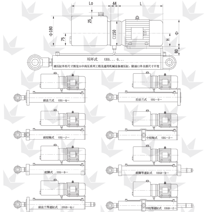
Table 5
Motor power: kW |
0.55 |
0.75 |
1.1 |
1.5 |
2.0 |
2.2 |
3.0 |
4.0 |
5.5 |
7.5 |
11 |
15 |
Φ |
175 |
175 |
195 |
195 |
195 |
215 |
215 |
240 |
275 |
275 |
335 |
335 |
H |
80 |
80 |
90 |
90 |
90 |
100 |
100 |
112 |
132 |
132 |
160 |
160 |
L |
275 |
275 |
280 |
305 |
320 |
370 |
370 |
380 |
475 |
515 |
605 |
650 |
|
Lo = 0.00005 × d² × s Lo – Oil Tank Length (mm), d – Piston Rod Diameter (mm), s – Stroke (mm)
The minimum value of Lo is 220 mm. For each subsequent size, add 100 mm, resulting in 220, 320, 420, 520, …
|