Foundational Architecture of a Servo Hydraulic System
Integrated Power Unit, Servo Valve, Actuator, and Feedback Sensor Layout
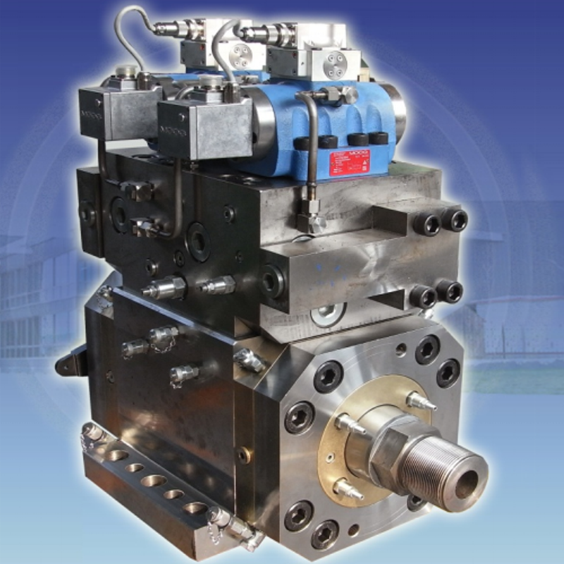
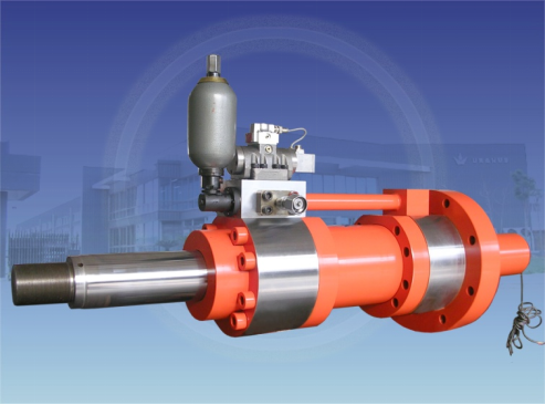
A servo hydraulic system’s core architecture integrates four interdependent components: the power unit, servo valve, actuator, and feedback sensor. The power unit—typically a variable-displacement pump driven by a motor—generates controlled, pressurized hydraulic fluid. The servo valve, acting as the electro-hydraulic translator, precisely modulates flow direction and volume in response to electronic control signals. This regulated fluid drives the actuator (cylinder or rotary motor), converting hydraulic energy into high-force, high-accuracy mechanical motion. Real-time position, velocity, or force feedback is provided by sensors such as linear variable differential transformers (LVDTs) or high-resolution optical encoders—enabling closed-loop correction with sub-millimeter repeatability. In applications like precision metal stamping, this architecture achieves ±0.1 mm positional accuracy by continuously compensating for thermal drift, compliance, and load-induced deflection.
Signal Flow from Command Input to Force/Position Output: The Electro-Hydraulic Interface
The control sequence begins with a command signal—typically a voltage or digital setpoint from a PLC or motion controller—which is translated into spool displacement within the servo valve. This action directs pressurized fluid to the appropriate actuator chamber, creating the pressure differential needed for motion. As the actuator moves, feedback sensors relay actual position or force data to the controller, which computes error and issues corrective output. Stability hinges on precise calibration: uncorrected valve deadband, for example, can induce oscillations exceeding ±2% of setpoint in high-inertia systems. While fluid compressibility and mechanical inertia inherently limit bandwidth, modern controllers use predictive algorithms—including adaptive gain scheduling—to maintain stability during rapid 0–100% load transitions without sacrificing response fidelity.
Critical Design Drivers for High-Performance Servo Hydraulic Systems
Dynamic Response, Bandwidth Limitations, and Closed-Loop Stability Requirements
High-performance servo hydraulic systems are defined by three tightly coupled design imperatives: dynamic response speed, usable bandwidth, and closed-loop stability. Bandwidth—the frequency at which system gain drops by 3 dB—is typically constrained to 15–30 Hz in high-inertia industrial applications due to hydraulic resonance, fluid compressibility, and valve/actuator dynamics. Exceeding these limits risks phase lag, overshoot, and instability; in forging presses, overshoot ≥5% can compromise part integrity or damage tooling. Leading designs address this through rigorous modeling of pressure wave propagation and resonant modes, combined with advanced control strategies. Adaptive gain scheduling, for instance, reduces overshoot by 40% compared to fixed-parameter PID while sustaining <1 ms control latency—enabling robust performance across varying loads and speeds.
Energy Efficiency Strategies: Regenerative Circuits, Load-Sensing, and Heat Dissipation
Energy efficiency is no longer ancillary—it’s integral to system viability. Regenerative circuits recover inertial energy during deceleration, redirecting up to 65% of otherwise dissipated power back into the system. Load-sensing pumps dynamically match flow and pressure to real-time actuator demand, eliminating wasteful throttling losses. Thermal management is equally critical: compact heat exchangers paired with optimized oil volumes reduce thermal load by 30%; variable-speed drives cut pump idle energy consumption by 55% versus fixed-displacement units; and smart cylinder designs—featuring laminar-flow internal passages—minimize viscous losses. Together, these strategies deliver up to 70% system-wide energy savings while maintaining ISO 4413-compliant thermal stability and long-term fluid integrity.
IIoT-Ready Integration and Smart Diagnostics in Modern Servo Hydraulic Systems
Modern servo hydraulic systems embed Industrial Internet of Things (IIoT) capabilities to transform reactive maintenance into proactive, data-driven operation. Onboard pressure, temperature, flow, and vibration sensors feed real-time telemetry to edge processors, where predictive algorithms identify early-stage anomalies—such as valve spool wear or accumulator gas loss—before they escalate into failures. Cloud-connected dashboards enable remote health monitoring and diagnostics, reducing unplanned downtime by up to 45%. Advanced analytics correlate multi-sensor data streams to optimize energy use, detect subtle deviations in motion profiles, and even auto-tune control parameters—for example, adjusting valve response curves based on fluid viscosity changes measured in situ. This convergence of edge intelligence and hydraulic actuation enables condition-based maintenance, extending component life and sustaining precision performance across demanding duty cycles.
Component Sizing and Selection Best Practices for Industrial Servo Hydraulic Applications
Pump, Cylinder, Accumulator, and Proportional-Servo Valve Sizing Based on Load Profile and Duty Cycle
Optimal component sizing balances performance, efficiency, and longevity—and must be anchored to the application’s actual load profile and duty cycle. Pumps must supply peak flow at required pressure without chronic overcapacity; undersizing causes pressure collapse under load, while oversizing increases heat, noise, and energy waste. Accumulators, sized for surge absorption and energy recovery, can be reduced by up to 30% in intermittent-duty applications versus continuous operation. Cylinder bore and stroke are determined by force and velocity requirements, with rod diameter carefully selected to prevent buckling under compressive loads. Servo valves must meet system bandwidth demands: for high-dynamic tasks like robotic material handling, valves with <10 ms response time and sufficient flow capacity are essential. The following framework guides selection:
| Component | Key Sizing Factor | Duty Cycle Consideration |
|---|---|---|
| Pump | Flow rate at peak pressure | Continuous vs. intermittent power |
| Cylinder | Force/stroke length at max speed | Seal wear under cyclic loading |
| Accumulator | Fluid volume for surge absorption | Pre-charge pressure maintenance |
| Servo Valve | Bandwidth vs. system response | Heat dissipation during cycling |
Transducer Resolution, Controller Sampling Rate, and Real-Time Tuning for Precision Motion Control
Micron-level motion control demands proportional fidelity across the entire signal chain. Transducer resolution must exceed target accuracy by at least 5×—so a ±5 μm positional tolerance requires ≤1 μm sensor resolution. Controller sampling rates must be 5–10× the system’s effective bandwidth to avoid aliasing and phase lag; for a 100 Hz bandwidth system, 500–1000 Hz sampling is mandatory. Real-time tuning—using adaptive PID algorithms—dynamically adjusts gains in response to changing friction, load, or temperature, cutting settling time by 40% in variable-condition environments. Vibration analysis during commissioning helps identify and suppress mechanical resonances, ensuring stable, jitter-free motion across the full operating envelope.
FAQ
What are the main components of a servo hydraulic system?
The main components of a servo hydraulic system are the power unit, servo valve, actuator, and feedback sensor.
How does a servo hydraulic system achieve high positional accuracy?
The system achieves high positional accuracy through real-time feedback and closed-loop correction that compensates for thermal drift, compliance, and load-induced deflection.
What are some energy efficiency strategies in servo hydraulic systems?
Energy efficiency strategies include regenerative circuits, load-sensing pumps, compact heat exchangers, and variable-speed drives.
How are IIoT and smart diagnostics integrated into modern servo hydraulic systems?
IIoT and smart diagnostics are integrated through onboard sensors and real-time telemetry that enable predictive maintenance and optimize system performance.
What is important for component sizing in industrial servo hydraulic applications?
Component sizing should consider the application’s load profile and duty cycle, balancing performance, efficiency, and longevity.
Table of Contents
- Foundational Architecture of a Servo Hydraulic System
- Critical Design Drivers for High-Performance Servo Hydraulic Systems
- IIoT-Ready Integration and Smart Diagnostics in Modern Servo Hydraulic Systems
- Component Sizing and Selection Best Practices for Industrial Servo Hydraulic Applications
-
FAQ
- What are the main components of a servo hydraulic system?
- How does a servo hydraulic system achieve high positional accuracy?
- What are some energy efficiency strategies in servo hydraulic systems?
- How are IIoT and smart diagnostics integrated into modern servo hydraulic systems?
- What is important for component sizing in industrial servo hydraulic applications?