
 EN
EN
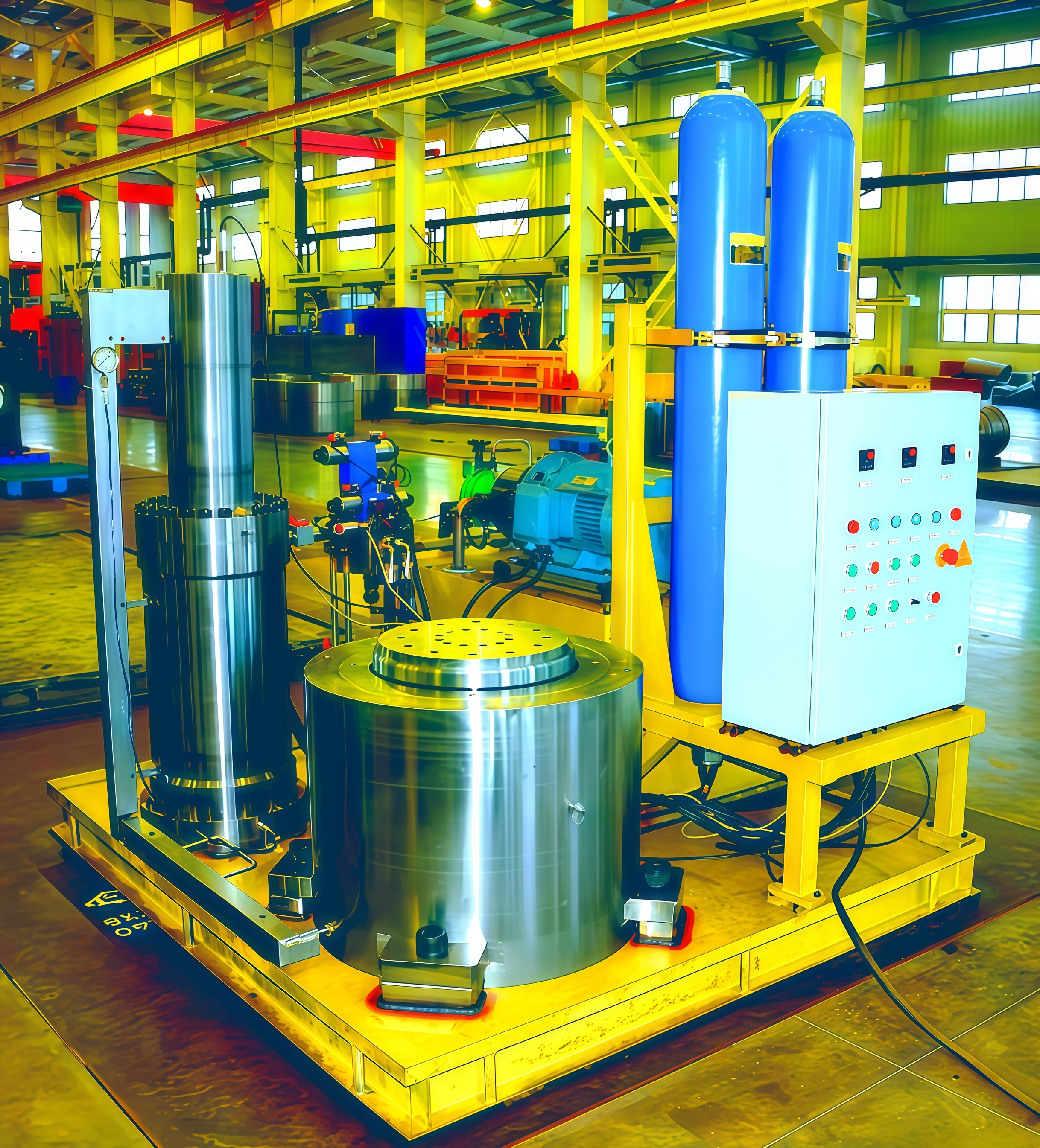
Booster Cylinder Guide: Enabling Reliable 630 MPa Hydrostatic Testing for Valve Bodies
Introduction: The Challenge of 630 MPa Hydrostatic Testing
Hydrostatic testing at 630 MPa (91,000 psi) represents one of the most demanding pressure validation processes in industrial manufacturing—particularly for oil and gas valve bodies, subsea equipment, and critical pressure vessels. Standard hydraulic power units typically supply only 25–35 MPa, making pressure amplification essential.
The booster cylinder is the core technology that enables this extreme pressure generation. Through precision engineering, advanced materials, and fail-safe design, modern booster cylinders deliver consistent, repeatable 630 MPa test pressures while maintaining operator safety and equipment integrity.
This guide explores the key design principles, material science, testing standards, and performance advantages of booster cylinders for high-pressure hydrostatic testing applications. [Internal Link: Explore our booster cylinder product range]
1. Ultra-High-Strength Material Selection and Forged Monobloc Construction
Achieving reliable 630 MPa hydrostatic pressure for valve body testing demands materials with exceptional strength and structural integrity.
Material Specifications
Booster cylinders use ultra-high-strength alloys with yield strengths exceeding 1,800 MPa:
| Material Type | Examples | Key Properties |
|---|---|---|
| Maraging steel | 18Ni (250/300/350 grades) | Exceptional toughness; age-hardened to 1,900 MPa |
| Precipitation-hardened stainless | 17-4PH, 15-5PH | Corrosion resistance; high strength; good fracture toughness |
Forged Monobloc Construction
The entire cylinder body is machined from a single forging, eliminating:
Weld seams
Threaded joints
Why this matters: According to a 2023 industry analysis of high-pressure cylinder failures, over 70% of fatigue fractures originate at weld seams and threaded joints under extreme cyclic loading.
Additional benefits:
Grain flow alignment – Forging aligns grain structure with part geometry, minimizing stress concentrations
Full-volume ultrasonic inspection – No blind spots for NDT (non-destructive testing)
Low-temperature ductility – Charpy impact testing at –40°C validates performance in cold service
Given the immense stored energy at 630 MPa—even microscopic flaws pose catastrophic risk—this combination of premium alloy selection and seamless fabrication is foundational to safe, repeatable performance.
2. Multi-Stage Hydraulic Amplification Architecture
Delivering 630 MPa from a standard hydraulic power unit (25–35 MPa) requires precise, scalable pressure amplification.
T-Series Tandem-Piston Architecture
T-series booster cylinders employ a tandem-piston design:
A large-diameter, low-pressure piston drives a smaller high-pressure plunger
Area ratio exceeding 20:1
Achieves intermediate and final pressure stages in sequence
| Feature | Benefit |
|---|---|
| Staged approach | Avoids shock loads and seal degradation common in single-stage intensifiers |
| Advanced chevron seals | Filled PTFE and UHMWPE; maintain low friction and integrity up to 700 MPa |
| Dedicated sequence valve manifold | Manages hydraulic synchronization across stages; ensures smooth, controlled ramp-up |
| Isolation of ultra-high-pressure section | Enhances operational safety and pressure stability during extended hold phases |
Performance data: A 2024 reliability study shows properly staged boosters achieve a mean time between failures (MTBF) of over 15,000 cycles—more than triple that of single-stage alternatives.
3. Finite Element Analysis: <0.012% Deformation Under Full Load
Structural integrity at 630 MPa is validated rigorously through finite element analysis (FEA) , modeling the full multi-stage intensifier and pressure containment shell.
FEA Validation Results
| Parameter | Result |
|---|---|
| Maximum principal deformation | Consistently below 0.012% of critical dimensions |
| Stress margin | Well within elastic limit of forged monobloc material |
| Safety factor | Verified 2.5 at rated pressure (meets ASME B&PV Code Section VIII Division 2) |
| Design optimization | Wall thickness transitions and fillet radii refined to eliminate stress risers |
Business Impact
Beyond validation, FEA-driven geometry refinement:
Reduces prototyping iterations – Slashes validation time by up to 60% (2023 industry field data)
Enables faster deployment – Test rigs with guaranteed dimensional stability and repeatability
4. ASME B16.34 and ISO 5211 Alignment for Valve Body Certification
For hydrostatic testing of valve bodies at 630 MPa, seamless integration with certification standards is non-negotiable.
Dual-Standard Compliance
The booster cylinder‘s outlet flange and mechanical interface are precision-machined to comply simultaneously with:
| Standard | Scope |
|---|---|
| ASME B16.34 | Steel valve pressure-temperature ratings |
| ISO 5211 | Actuator mounting dimensions |
Benefits of Integrated Compliance
Eliminates field-fabricated adapters – Common sources of leakage paths and misalignment-induced stresses
Direct certification – Valve manufacturers can certify products directly without re-qualifying the test apparatus
High first-pass rate – Independent quality audits confirm 98% first-pass certification for API 6A and 6D valve bodies
Embedding compliance into the booster cylinder‘s core design significantly reduces integration costs, accelerates commissioning, and strengthens confidence during third-party witness inspections.
5. Energy Containment Calculations and Fail-Safe Rig Design
At 630 MPa, the elastic energy stored in compressed fluid and stressed components reaches hazardous levels—making fail-safe engineering essential.
Fail-Safe Design Elements
| Safety Feature | Function |
|---|---|
| Burst shield specifications | Contains energy release in case of catastrophic failure |
| Pressure-relief valve setpoints | Prevents over-pressurization |
| Remote monitoring thresholds | Enables safe operation from control room |
| Automatic circuit isolation | Booster cylinder control system isolates hydraulic circuit upon failure |
| Certified containment enclosure | Directs energy release safely |
Design Validation
All pressure boundaries undergo burst pressure analysis
Ensures the weakest link fails predictably and controllably—not explosively
Regulatory Alignment
These safeguards align with:
OSHA-compliant process safety management practices
ASME B16.34/ISO 5211 certification workflows
The result: reduced operator risk and prevention of collateral equipment damage.
6. Performance Advantages Over Conventional Systems
Compared to conventional intensifier-driven or direct-pump systems, the booster cylinder delivers measurable gains:
| Metric | Booster Cylinder | Conventional System |
|---|---|---|
| Precision | Fine-grained pressure ramp-up; stable hold phases | Coarser control; more variability |
| Energy consumption | 25–35% lower per cycle | Higher due to single-stage inefficiency |
| Leak paths | Minimal (monobloc construction) | Multiple (bolted/welded assemblies) |
| Deformation at full load | <0.012% (FEA-validated) | Higher; more dimensional change |
| Maintenance intervals | Extended (isolated high-pressure chamber) | Shorter (exposed pump plungers) |
| Safety | Integrated fail-safe features | Limited or external protection only |
Result: Lower total cost of ownership, shorter test cycles, and consistent, auditable proof tests for safety-critical valve bodies.
7. Applications and Use Cases
| Industry | Application | Why Booster Cylinder |
|---|---|---|
| Oil & Gas | API 6A/6D valve body testing | 630 MPa validation; ASME/ISO compliance |
| Subsea equipment | Pressure vessel certification | Ultra-high pressure; fail-safe design |
| Aerospace | Hydraulic component testing | Precision control; repeatable cycles |
| Power generation | Valve and fitting proof testing | High cycle count; reliable MTBF |
| Research & development | Material characterization | Accurate pressure ramp profiles |
8. Maintenance and Service Life
To maximize booster cylinder service life:
| Practice | Frequency | Benefit |
|---|---|---|
| Seal inspection (chevron seals) | Every 2,000 cycles | Detects wear; prevents leaks |
| Oil cleanliness monitoring | Continuous (ISO 4406 16/14/11 target) | Protects internal surfaces; extends life |
| Pressure relief valve testing | Annually | Ensures setpoint accuracy |
| Burst shield inspection | Annually | Verifies containment integrity |
| Full system proof test | Every 10,000 cycles | Validates overall system integrity |
With proper maintenance, booster cylinders typically achieve service life exceeding 5 years in high-cycle production testing environments.
FAQ
What is a booster cylinder?
A booster cylinder is a device designed to amplify hydraulic pressure from a standard level (e.g., 25–35 MPa) to ultra-high levels like 630 MPa for specialized applications such as valve body hydrostatic testing. It uses a multi-stage piston system to achieve this pressure amplification efficiently and safely.
Why is monobloc construction important for booster cylinders?
Monobloc construction, formed from a single forging, eliminates weak points like seams and joints. This contributes to greater structural integrity, minimizing the risk of failure under high-pressure conditions.
How does multi-stage architecture benefit hydrostatic testing?
Multi-stage architecture in booster cylinders enables smooth pressure ramp-up, reduces wear and tear on seals, and improves the overall mean time between failures (MTBF) compared to single-stage systems.
What role does FEA play in booster cylinder design?
Finite Element Analysis (FEA) helps validate structural integrity under simulated pressure conditions, optimizing design features like wall thickness and geometry to ensure safe operation at rated pressures.
How do compliance standards enhance performance?
By adhering to ASME B16.34 and ISO 5211 standards, booster cylinders eliminate the need for custom adapters, reduce integration costs, and streamline valve certification workflows.
What safety features are integrated into booster cylinder systems?
Booster cylinder systems include burst shields, pressure-relief valves, remote monitoring, automatic circuit isolation, and certified containment enclosures to protect operators and equipment.
Conclusion: Choose Booster Cylinders for Reliable Ultra-High-Pressure Testing
The booster cylinder is the enabling technology behind reliable 630 MPa hydrostatic testing. Through forged monobloc construction, multi-stage amplification, FEA-validated design, ASME/ISO compliance, and integrated fail-safe features, modern booster cylinders deliver the performance, safety, and repeatability required for critical valve body certification.
Whether you are testing API 6A wellhead equipment, subsea valves, or aerospace components, a properly designed booster cylinder system ensures accurate, reliable, and safe pressure validation.
Ready to specify a booster cylinder for your test rig? [Contact our engineering team] for technical specifications, sizing assistance, and a free consultation.
[Internal Link: Browse our complete booster cylinder product lineup]
Table of Contents
- Introduction: The Challenge of 630 MPa Hydrostatic Testing
- 1. Ultra-High-Strength Material Selection and Forged Monobloc Construction
- 2. Multi-Stage Hydraulic Amplification Architecture
- 3. Finite Element Analysis: <0.012% Deformation Under Full Load
- 4. ASME B16.34 and ISO 5211 Alignment for Valve Body Certification
- 5. Energy Containment Calculations and Fail-Safe Rig Design
- 6. Performance Advantages Over Conventional Systems
- 7. Applications and Use Cases
- 8. Maintenance and Service Life
- FAQ
- Conclusion: Choose Booster Cylinders for Reliable Ultra-High-Pressure Testing