Página De Inicio > Productos > Cilindros hidráulicos personalizados


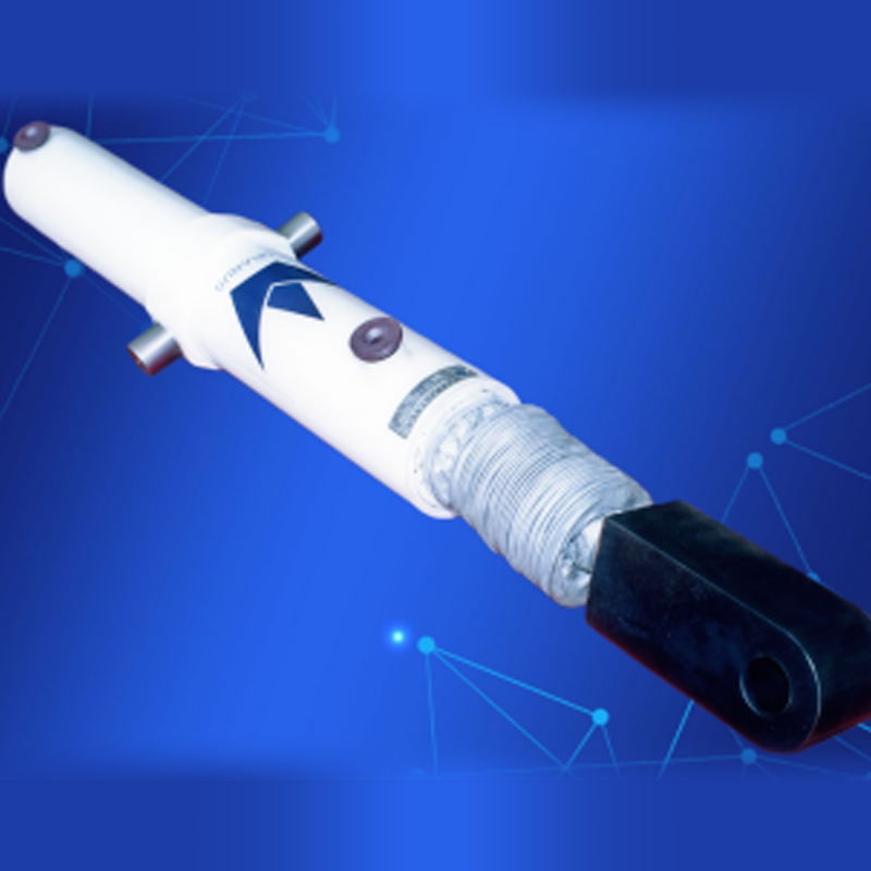
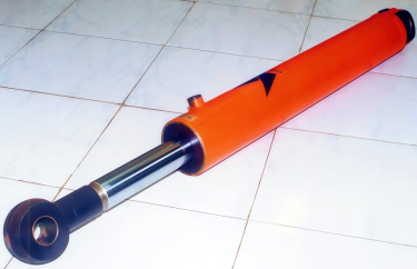
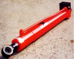
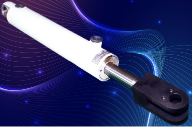
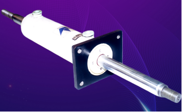
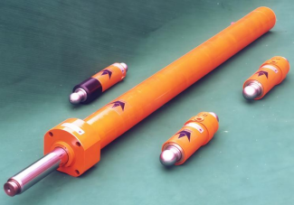
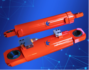
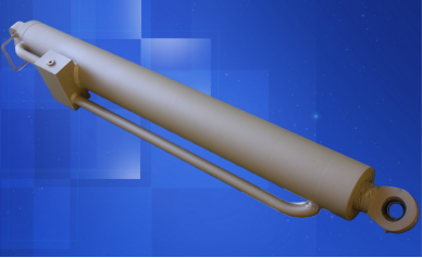
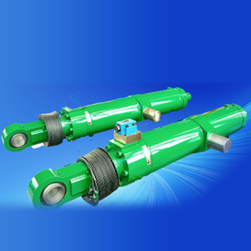
Fotos de cilindros hidráulicos para maquinaria de construcción 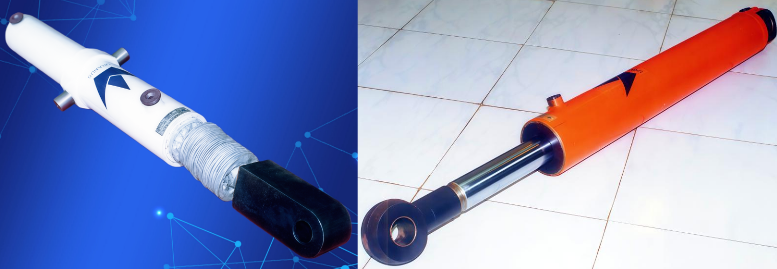
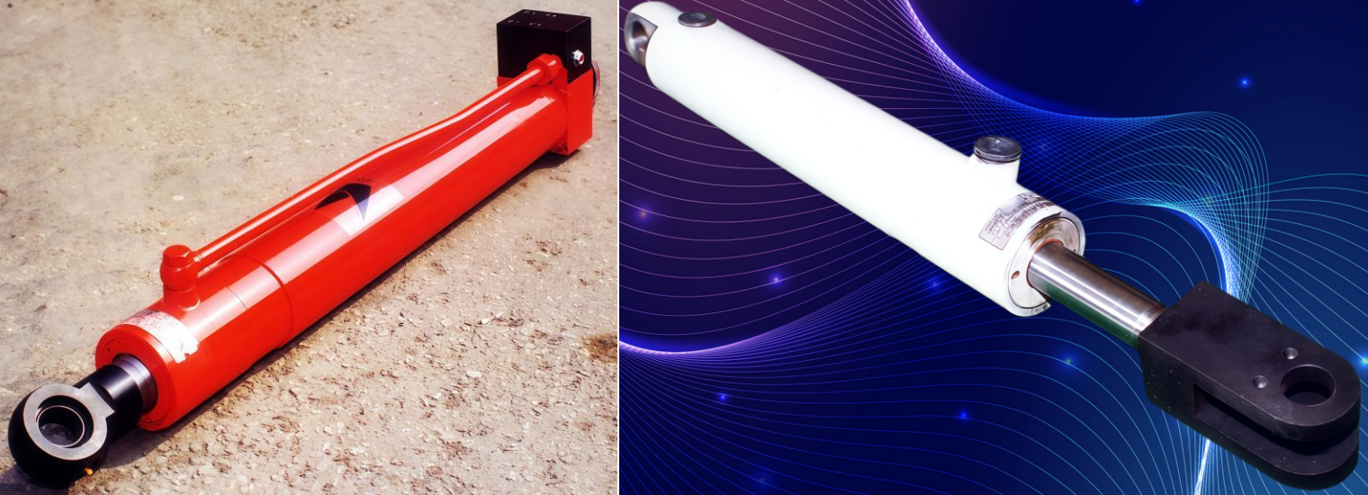
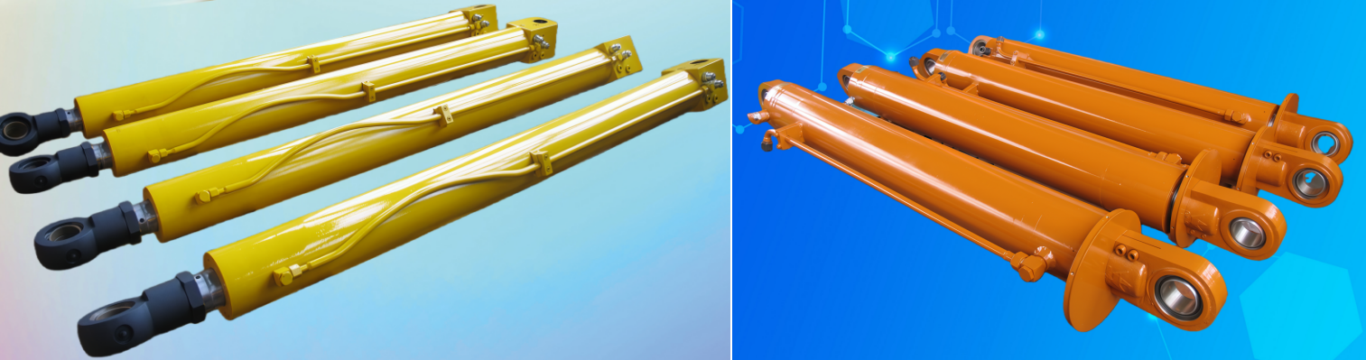
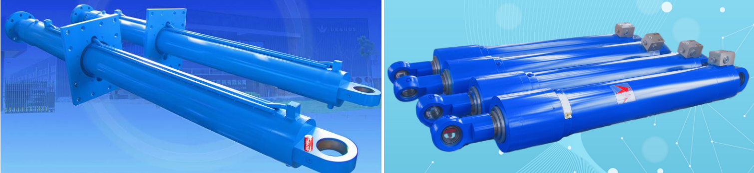
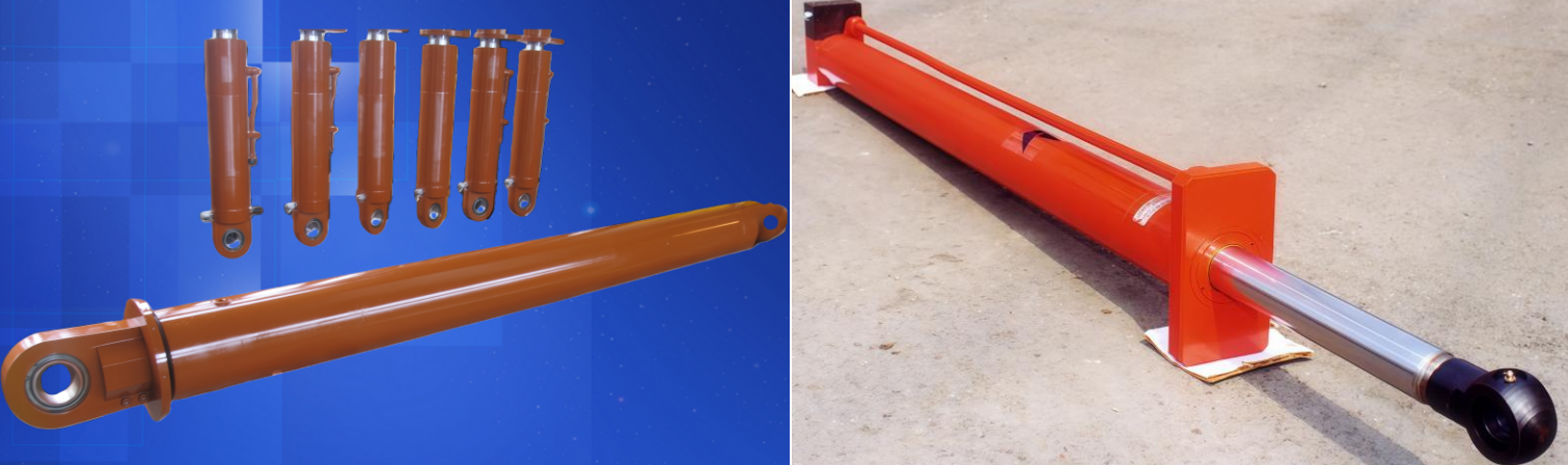
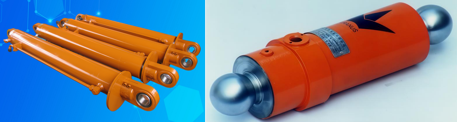
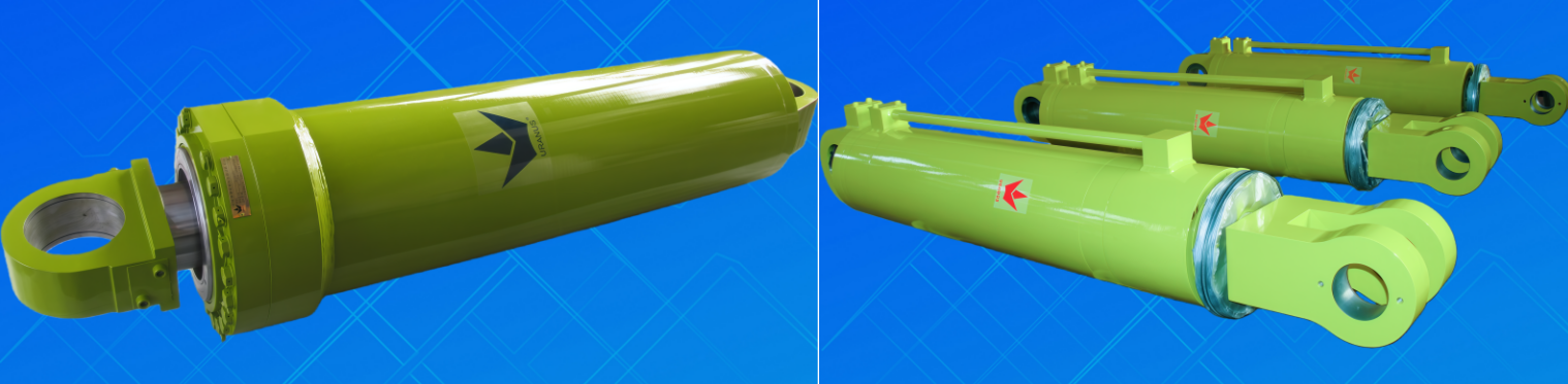

Cilindros Hidráulicos de Media y Alta Presión Serie UG
Una Plataforma Estandarizada de Cilindros Hidráulicos Basada en Décadas de Experiencia en Ingeniería Personalizada
Descripción del producto
El Los cilindros hidráulicos de media y alta presión serie UG son desarrollados independientemente por Uranus Hydraulic basándose en décadas de amplia experiencia en la fabricación a gran escala de cilindros hidráulicos personalizados.
Diseñada sobre una plataforma estructural estandarizada y manteniendo una alta modularidad y flexibilidad de configuración, la serie UG es adecuada para maquinaria de construcción, equipos industriales y aplicaciones pesadas. Esta serie integra exitosamente la capacidad de ingeniería personalizada con la producción industrial estandarizada, ofreciendo un rendimiento estable, alta confiabilidad y larga vida útil.
Especificaciones clave y configuraciones
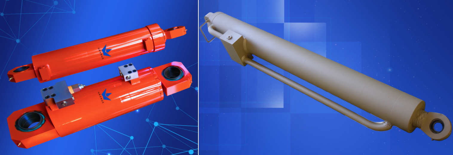
Tipos funcionales
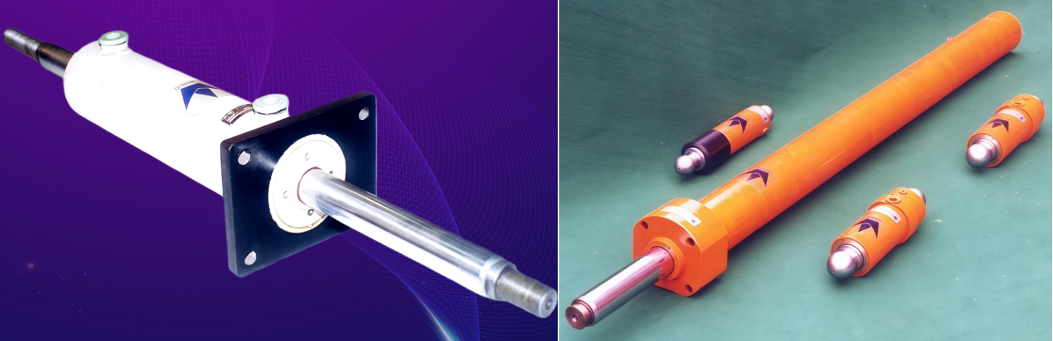
Estilos de montaje
・Montaje con horquilla delantera
・Montaje central con ojo transversal
・Montaje frontal con brida
・Montaje trasero con brida
・Montaje sobre patas
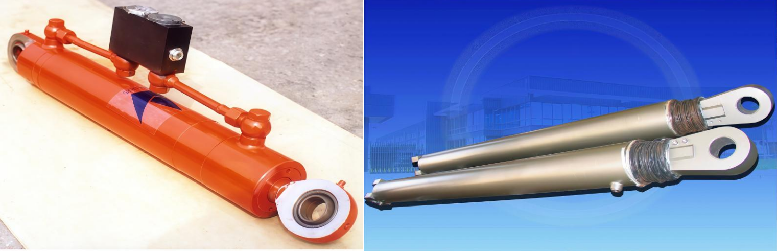
Conexiones de extremo de vástago
・Extremo de vástago roscado
・Ojal con buje autolubricante
・Ojal con cojinete esférico
Presiones nominales y dimensiones
・Presión nominal: 16 MPa / 21 MPa
・Diámetro del cilindro: φ40 – φ250 mm (15 tamaños)
・Diámetro del vástago: φ20 – φ180 mm (23 tamaños)
・Carrera máxima: hasta 10 m (sujeto a las condiciones de estabilidad del vástago)
Capacidad de fabricación
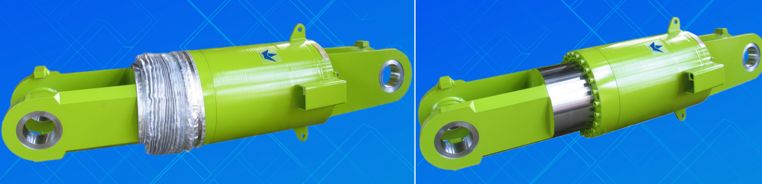
Los componentes clave de los cilindros hidráulicos de la serie UG, incluidos vástagos, tubos de cilindro, pistones, cabezales y tapas finales, se fabrican utilizando centros de mecanizado CNC de precisión y se controlan bajo estrictos procedimientos de gestión de calidad.
Todos los cilindros están equipados con sistemas de sellado premium de baja fricción y alta resistencia al desgaste, lo que garantiza un funcionamiento estable bajo cargas elevadas, impactos y condiciones exigentes de trabajo.
Control de Calidad y Pruebas
Cada cilindro hidráulico de la serie UG pasa por pruebas completas de rendimiento antes de la entrega, centradas en:
・Cero fugas externas
・Alta eficiencia mecánica
・Excelente resistencia a choques y vibraciones
・Larga vida útil
Todos los planos de productos, registros de inspección y informes de pruebas se archivan durante más de 10 años , asegurando trazabilidad completa y verificación de calidad.
Compromiso de Calidad de Por Vida
Para cualquier problema de calidad causado por defectos de diseño o fabricación, Uranus Hydraulic ofrece reparación o reemplazo gratuito de por vida, brindando confiabilidad a largo plazo y seguridad a los clientes.
Acerca de Uranus Hydraulic
Fundado en 1995, Uranus Hydraulic es un fabricante orientado a la tecnología especializado en productos de transmisión hidráulica de gama alta y equipos inteligentes mecatrónicos que integran mecánica, hidráulica, óptica y electrónica.
La empresa ha archivado más de 50.000 juegos de dibujos técnicos personalizados, contiene más de 100 patentes nacionales de invención y modelos de utilidad , y opera con software de diseño paramétrico 3D, sistemas de gestión del ciclo de vida del producto (PDM) y sistemas ERP continuamente optimizados.
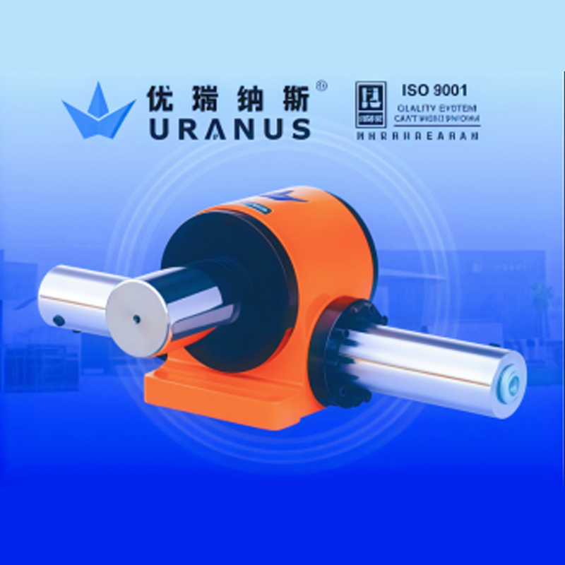
Uranus Hydraulic cuenta con certificación ISO 9001, ISO 14001 e ISO 45001, y sus productos son ampliamente confiables para clientes en todo el mundo por su sofisticación técnica y calidad constante.
Series de productos relacionados
・Cilindros hidráulicos serie UY para aplicaciones pesadas y metalurgia (25 MPa)
・Cilindros servo serie US con sensores magnetoestrictivos integrados
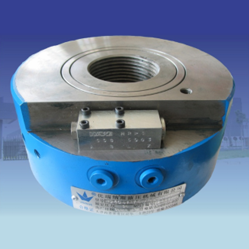
・Cilindros hidráulicos rotativos serie UB de cremallera y piñón
・Conexiones rotativas serie UX de alta presión con múltiples pasos
・Unidades de potencia hidráulica serie UP
・Cilindro hidráulico distribuidor sincrónico serie UF
・Cilindros electrohidráulicos serie UE
Cilindros hidráulicos para equipos de maquinaria general e ingeniería, serie UG de media y alta presión 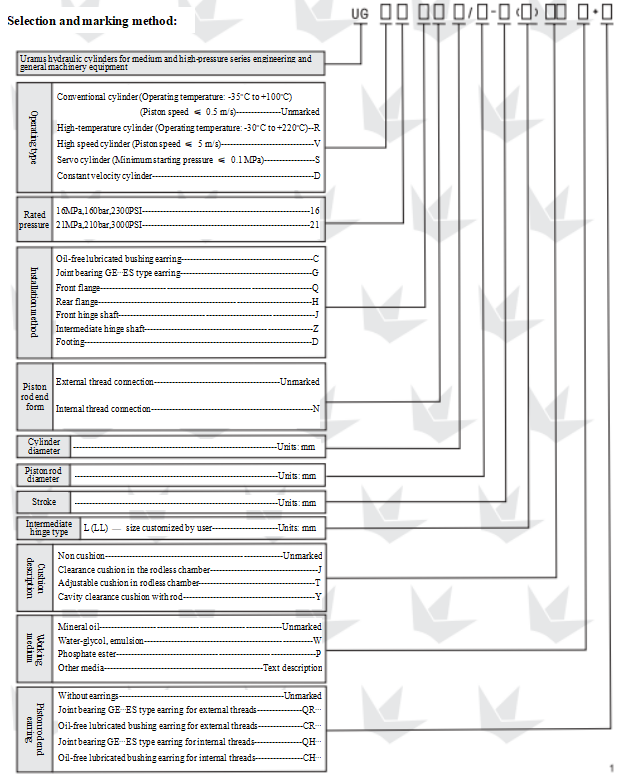
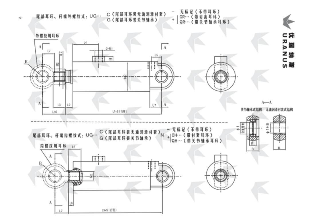
UG…C…bujía lubricada sin aceite tipo pendiente, UG…G…rodamiento de articulación (tipo GE..ES) tipo pendiente
Diámetro del cilindro |
Diámetro de la varilla |
∅1 |
∅2 |
∅7 |
L1 |
El 2 |
L3 |
El número de |
L5 |
L6 |
L7 |
L9 |
L16 |
Barra |
B |
B1 |
H |
M |
M2 |
Extremo de vástago tipo pendiente |
|||||
Dimensiones |
Tolerancia del agujero del rodamiento |
Sin amortiguación |
Amortiguación Y |
Cr |
Qr |
Ch |
QH |
||||||||||||||||||
40 |
20 |
20 |
0-0.010 |
58 |
25 |
200 |
16 |
25 |
70 |
59 |
30 |
10 |
30 |
190 |
50 |
25 |
16 |
12 |
M18×1.5 |
M14×1.5 |
40-1 |
||||
22 |
28 |
M16×1.5 |
-2 |
||||||||||||||||||||||
28 |
35 |
M22×1.5 |
-3 |
||||||||||||||||||||||
50 |
25 |
30 |
70 |
28 |
205 |
18 |
30 |
58 |
35 |
40 |
195 |
60 |
35 |
22 |
M20×1.5 |
50-1 |
|||||||||
28 |
35 |
M22×1.5 |
-2 |
||||||||||||||||||||||
36 |
42 |
M27×2 |
-3 |
||||||||||||||||||||||
63 |
32 |
83 |
35 |
245 |
20 |
35 |
73 |
76 |
40 |
15 |
235 |
65 |
15 |
M22×1.5 |
M24×1.5 |
63-1 |
|||||||||
36 |
42 |
M27×2 |
-2 |
||||||||||||||||||||||
45 |
45 |
M33×2 |
-3 |
||||||||||||||||||||||
80 |
40 |
40 |
0-0.012 |
108 |
42 |
260 |
45 |
75 |
45 |
18 |
55 |
255 |
105 |
45 |
28 |
M30×2 |
80-1 |
||||||||
45 |
48 |
M33×2 |
-2 |
||||||||||||||||||||||
56 |
60 |
M42×2 |
-3 |
||||||||||||||||||||||
90 |
45 |
114 |
48 |
78 |
110 |
M33×2 |
90-1 |
||||||||||||||||||
50 |
52 |
M36×2 |
-2 |
||||||||||||||||||||||
63 |
68 |
M48×2 |
-3 |
||||||||||||||||||||||
100 |
50 |
50 |
127 |
52 |
300 |
50 |
89 |
85 |
55 |
70 |
295 |
130 |
60 |
35 |
20 |
M27×2 |
M36×2 |
100-1 |
|||||||
56 |
60 |
M42×2 |
-2 |
||||||||||||||||||||||
70 |
72 |
M52×2 |
-3 |
||||||||||||||||||||||
110 |
56 |
140 |
60 |
305 |
55 |
90 |
90 |
300 |
135 |
M42×2 |
110-1 |
||||||||||||||
63 |
68 |
M48×2 |
-2 |
||||||||||||||||||||||
80 |
80 |
M60×2 |
-3 |
||||||||||||||||||||||
125 |
63 |
152 |
68 |
315 |
60 |
104 |
87 |
310 |
140 |
M48×2 |
125-1 |
||||||||||||||
70 |
72 |
M52×2 |
-2 |
||||||||||||||||||||||
90 |
90 |
M68×2 |
-3 |
||||||||||||||||||||||
140 |
70 |
60 |
0-0.015 |
168 |
72 |
345 |
65 |
114 |
105 |
65 |
80 |
340 |
155 |
70 |
44 |
M33×2 |
M52×2 |
145-1 |
|||||||
80 |
80 |
M60×2 |
-2 |
||||||||||||||||||||||
100 |
100 |
M76×3 |
-3 |
||||||||||||||||||||||
150 |
75 |
180 |
76 |
350 |
70 |
119 |
110 |
345 |
157 |
M56×2 |
150-1 |
||||||||||||||
85 |
85 |
M64×2 |
-2 |
||||||||||||||||||||||
105 |
105 |
M80×3 |
-3 |
||||||||||||||||||||||
160 |
80 |
194 |
80 |
355 |
75 |
124 |
115 |
350 |
160 |
M60×2 |
160-1 |
||||||||||||||
90 |
90 |
M68×2 |
-2 |
||||||||||||||||||||||
110 |
110 |
M85×3 |
-3 |
||||||||||||||||||||||
180 |
90 |
70 |
219 |
90 |
410 |
25 |
85 |
129 |
122 |
75 |
22 |
90 |
400 |
180 |
80 |
49 |
M42×2 |
M68×2 |
180-1 |
||||||
100 |
100 |
M76×3 |
-2 |
||||||||||||||||||||||
125 |
120 |
M95×3 |
-3 |
||||||||||||||||||||||
200 |
100 |
80 |
245 |
100 |
430 |
95 |
141 |
127 |
85 |
100 |
420 |
200 |
90 |
55 |
M76×3 |
200-1 |
|||||||||
110 |
110 |
M85×3 |
-2 |
||||||||||||||||||||||
140 |
125 |
M100×3 |
-3 |
||||||||||||||||||||||
220 |
110 |
90 |
0-0.020 |
272 |
110 |
465 |
105 |
146 |
143 |
90 |
110 |
455 |
225 |
100 |
60 |
25 |
M48×2 |
M85×3 |
220-1 |
||||||
125 |
120 |
M95×3 |
-2 |
||||||||||||||||||||||
160 |
140 |
M125×3 |
-3 |
||||||||||||||||||||||
250 |
125 |
100 |
299 |
120 |
485 |
115 |
155 |
100 |
120 |
475 |
245 |
110 |
70 |
M95×3 |
250-1 |
||||||||||
140 |
125 |
M100×3 |
-2 |
||||||||||||||||||||||
180 |
160 |
M145×3 |
-3 |
||||||||||||||||||||||
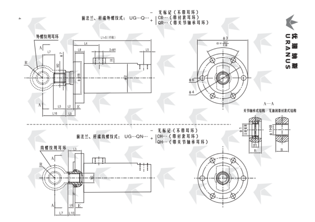
UG…Q tipo brida delantera
Diámetro del cilindro |
Diámetro de la varilla |
∅1 |
∅2 |
∅3 |
∅4 |
∅5 f8 |
∅6 |
∅7 |
L1 |
El 2 |
L3 |
El número de |
L5 |
L6 |
L7 |
L8 |
L9 |
L10 |
L16 |
E |
Barra |
B |
B1 |
H |
El número de unidades |
M2 |
Extremo de vástago tipo pendiente |
|||||
Dimensiones |
Tolerancia del agujero del rodamiento |
Sin amortiguación |
Amortiguación Y |
Cr |
Qr |
Ch |
QH |
|||||||||||||||||||||||||
40 |
20 |
20 |
0-0.010 |
58 |
104 |
84 |
64 |
6 orificios ∅ 11 |
25 |
167 |
16 |
25 |
70 |
59 |
17 |
10 |
30 |
20 |
21 |
15 |
50 |
5 |
25 |
16 |
12 |
M18×1.5 |
M14×1.5 |
40-1 |
||||
22 |
28 |
M16×1.5 |
-2 |
|||||||||||||||||||||||||||||
28 |
35 |
M22×1.5 |
-3 |
|||||||||||||||||||||||||||||
50 |
25 |
30 |
70 |
120 |
98 |
76 |
28 |
170 |
18 |
30 |
58 |
20 |
40 |
23 |
60 |
35 |
22 |
M20×1.5 |
50-1 |
|||||||||||||
28 |
35 |
M22×1.5 |
-2 |
|||||||||||||||||||||||||||||
36 |
42 |
M27×2 |
-3 |
|||||||||||||||||||||||||||||
63 |
32 |
83 |
140 |
115 |
90 |
6 orificios ∅ 13 |
35 |
200 |
20 |
35 |
73 |
76 |
15 |
25 |
25 |
20 |
65 |
15 |
M22×1.5 |
M24×1.5 |
63-1 |
|||||||||||
36 |
42 |
M27×2 |
-2 |
|||||||||||||||||||||||||||||
45 |
45 |
M33×2 |
-3 |
|||||||||||||||||||||||||||||
80 |
40 |
40 |
0-0.012 |
108 |
175 |
145 |
115 |
8 orificios ∅ 13.5 |
42 |
217 |
|
75 |
25 |
18 |
55 |
23 |
105 |
45 |
28 |
M30×2 |
80-1 |
|||||||||||
45 |
48 |
M33×2 |
-2 |
|||||||||||||||||||||||||||||
56 |
60 |
M42×2 |
-3 |
|||||||||||||||||||||||||||||
90 |
45 |
114 |
190 |
160 |
130 |
8 orificios ∅ 15.5 |
48 |
|
78 |
110 |
M33×2 |
90-1 |
||||||||||||||||||||
50 |
52 |
M36×2 |
-2 |
|||||||||||||||||||||||||||||
63 |
68 |
M48×2 |
-3 |
|||||||||||||||||||||||||||||
100 |
50 |
50 |
127 |
210 |
180 |
145 |
8 orificios ∅ 18 |
52 |
252 |
50 |
89 |
85 |
30 |
70 |
30 |
130 |
60 |
35 |
20 |
M27×2 |
M36×2 |
100-1 |
||||||||||
56 |
60 |
M42×2 |
-2 |
|||||||||||||||||||||||||||||
70 |
72 |
M52×2 |
-3 |
|||||||||||||||||||||||||||||
110 |
56 |
140 |
225 |
195 |
160 |
60 |
257 |
55 |
90 |
90 |
135 |
M42×2 |
110-1 |
|||||||||||||||||||
63 |
68 |
M48×2 |
-2 |
|||||||||||||||||||||||||||||
80 |
80 |
M60×2 |
-3 |
|||||||||||||||||||||||||||||
125 |
63 |
152 |
240 |
210 |
175 |
10 orificios ∅ 18 |
68 |
267 |
60 |
104 |
87 |
40 |
140 |
M48×2 |
125-1 |
|||||||||||||||||
70 |
72 |
M52×2 |
-2 |
|||||||||||||||||||||||||||||
90 |
90 |
M68×2 |
-3 |
|||||||||||||||||||||||||||||
140 |
70 |
60 |
0-0.015 |
168 |
260 |
225 |
190 |
10 orificios ∅20 |
72 |
292 |
65 |
114 |
105 |
35 |
80 |
155 |
70 |
44 |
M33×2 |
M52×2 |
140-1 |
|||||||||||
80 |
80 |
M60×2 |
-2 |
|||||||||||||||||||||||||||||
100 |
100 |
M76×3 |
-3 |
|||||||||||||||||||||||||||||
150 |
75 |
180 |
285 |
245 |
205 |
10 orificios ∅ 22 |
76 |
297 |
70 |
119 |
110 |
157 |
M56×2 |
150-1 |
||||||||||||||||||
85 |
85 |
M64×2 |
-2 |
|||||||||||||||||||||||||||||
105 |
105 |
M80×3 |
-3 |
|||||||||||||||||||||||||||||
160 |
80 |
194 |
300 |
260 |
220 |
80 |
302 |
75 |
124 |
115 |
50 |
30 |
28 |
160 |
10 |
M60×2 |
160-1 |
|||||||||||||||
90 |
90 |
M68×2 |
-2 |
|||||||||||||||||||||||||||||
110 |
110 |
M85×3 |
-3 |
|||||||||||||||||||||||||||||
180 |
90 |
70 |
219 |
325 |
285 |
245 |
10 orificios ∅ 24 |
90 |
343 |
|
85 |
129 |
122 |
40 |
|
90 |
35 |
|
180 |
80 |
49 |
M42×2 |
M68×2 |
180-1 |
||||||||
100 |
100 |
M76×3 |
-2 |
|||||||||||||||||||||||||||||
125 |
120 |
M95×3 |
-3 |
|||||||||||||||||||||||||||||
200 |
100 |
80 |
245 |
365 |
320 |
275 |
10 orificios ∅ 26 |
100 |
353 |
95 |
141 |
127 |
100 |
60 |
200 |
90 |
55 |
M76×3 |
200-1 |
|||||||||||||
110 |
110 |
M85×3 |
-2 |
|||||||||||||||||||||||||||||
140 |
125 |
M100×3 |
-3 |
|||||||||||||||||||||||||||||
220 |
110 |
90 |
0-0.020 |
272 |
405 |
355 |
305 |
10 orificios ∅ 29 |
110 |
393 |
|
105 |
146 |
143 |
50 |
|
110 |
70 |
|
225 |
100 |
60 |
25 |
M48×2 |
M85×3 |
220-1 |
||||||
125 |
120 |
M95×3 |
-2 |
|||||||||||||||||||||||||||||
160 |
140 |
M125×3 |
-3 |
|||||||||||||||||||||||||||||
250 |
125 |
100 |
299 |
450 |
390 |
330 |
12 orificios ∅ 32 |
120 |
403 |
115 |
155 |
120 |
245 |
110 |
70 |
M95×3 |
250-1 |
|||||||||||||||
140 |
125 |
M100×3 |
-2 |
|||||||||||||||||||||||||||||
180 |
160 |
M145×3 |
-3 |
|||||||||||||||||||||||||||||
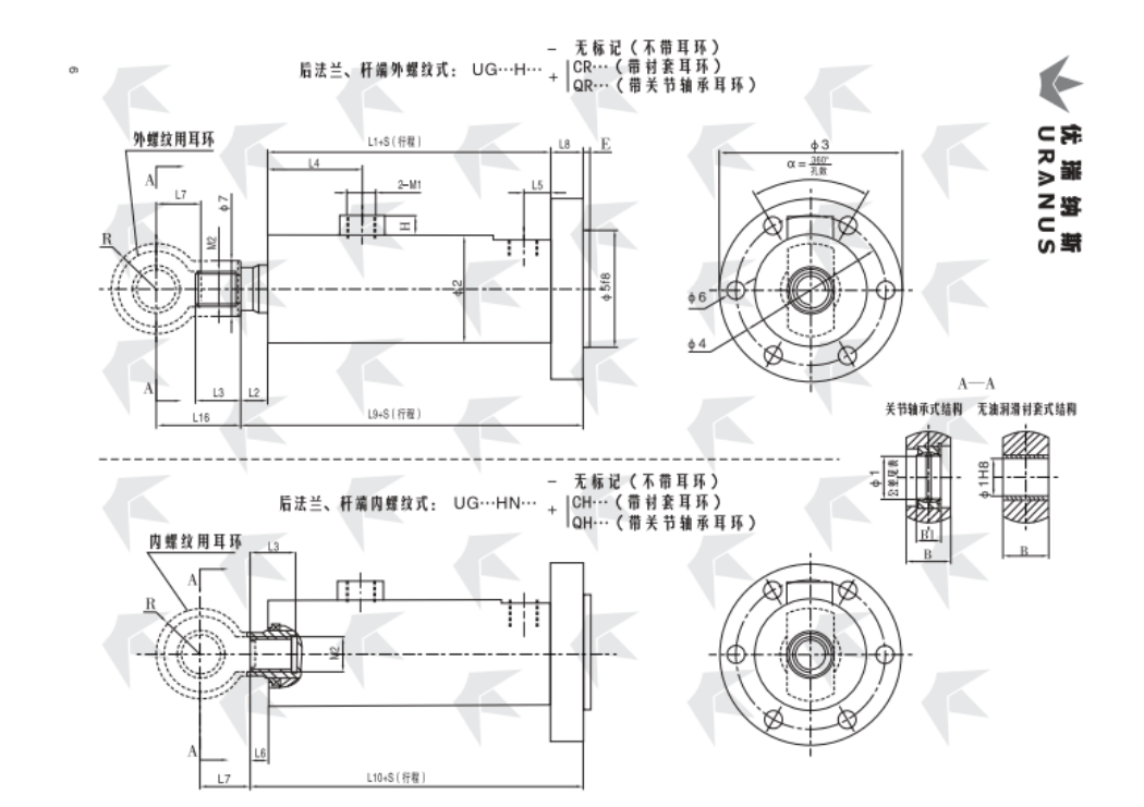
Tipo de brida trasera UG…H
Diámetro del cilindro |
Diámetro de la varilla |
∅1 |
∅2 |
∅3 |
∅4 |
∅5 f8 |
∅6 |
∅7 |
L1 |
El 2 |
L3 |
El número de |
L5 |
L6 |
L7 |
L8 |
L9 |
L10 |
L16 |
E |
Barra |
B |
B1 |
H |
El número de unidades |
M2 |
Extremo de vástago tipo pendiente |
|||||
Dimensiones |
Tolerancia del agujero del rodamiento |
Sin amortiguación |
Amortiguación Y |
Cr |
Qr |
Ch |
QH |
|||||||||||||||||||||||||
40 |
20 |
20 |
0-0.010 |
58 |
104 |
84 |
64 |
6 agujeros ∅ 11 |
25 |
167 |
16 |
25 |
70 |
59 |
17 |
10 |
30 |
20 |
203 |
197 |
50 |
5 |
25 |
16 |
12 |
M18×1.5 |
M14×1.5 |
40-1 |
||||
22 |
28 |
M16×1.5 |
-2 |
|||||||||||||||||||||||||||||
28 |
35 |
M22×1.5 |
-3 |
|||||||||||||||||||||||||||||
50 |
25 |
30 |
70 |
120 |
98 |
76 |
28 |
170 |
18 |
30 |
58 |
20 |
40 |
208 |
200 |
60 |
35 |
22 |
M20×1.5 |
50-1 |
||||||||||||
28 |
35 |
M22×1.5 |
-2 |
|||||||||||||||||||||||||||||
36 |
42 |
M27×2 |
-3 |
|||||||||||||||||||||||||||||
63 |
32 |
83 |
140 |
115 |
90 |
6 agujeros ∅ 13 |
35 |
200 |
20 |
35 |
73 |
76 |
15 |
25 |
245 |
240 |
65 |
15 |
M22×1.5 |
M24×1.5 |
63-1 |
|||||||||||
36 |
42 |
M27×2 |
-2 |
|||||||||||||||||||||||||||||
45 |
45 |
M33×2 |
-3 |
|||||||||||||||||||||||||||||
80 |
40 |
40 |
0-0.012 |
108 |
175 |
145 |
115 |
8 agujeros ∅ 13.5 |
42 |
217 |
45 |
75 |
25 |
18 |
55 |
262 |
260 |
105 |
45 |
28 |
M30×2 |
80-1 |
||||||||||
45 |
48 |
M33×2 |
-2 |
|||||||||||||||||||||||||||||
56 |
60 |
M42×2 |
-3 |
|||||||||||||||||||||||||||||
90 |
45 |
114 |
190 |
160 |
130 |
8 agujeros ∅ 15.5 |
48 |
78 |
110 |
M33×2 |
90-1 |
|||||||||||||||||||||
50 |
52 |
M36×2 |
-2 |
|||||||||||||||||||||||||||||
63 |
68 |
M48×2 |
-3 |
|||||||||||||||||||||||||||||
100 |
50 |
50 |
127 |
210 |
180 |
145 |
8 agujeros ∅ 18 |
52 |
252 |
50 |
89 |
85 |
30 |
70 |
30 |
302 |
300 |
130 |
60 |
35 |
20 |
M27×2 |
M36×2 |
100-1 |
||||||||
56 |
60 |
M42×2 |
-2 |
|||||||||||||||||||||||||||||
70 |
72 |
M52×2 |
-3 |
|||||||||||||||||||||||||||||
110 |
56 |
140 |
225 |
195 |
160 |
60 |
257 |
55 |
90 |
90 |
307 |
305 |
135 |
M42×2 |
110-1 |
|||||||||||||||||
63 |
M48×2 |
-2 |
||||||||||||||||||||||||||||||
80 |
80 |
M60×2 |
-3 |
|||||||||||||||||||||||||||||
125 |
63 |
152 |
240 |
210 |
175 |
10 Agujeros ∅ 18 |
68 |
267 |
60 |
104 |
87 |
40 |
327 |
325 |
140 |
M48×2 |
125-1 |
|||||||||||||||
70 |
72 |
M52×2 |
-2 |
|||||||||||||||||||||||||||||
90 |
90 |
M68×2 |
-3 |
|||||||||||||||||||||||||||||
140 |
70 |
60 |
0-0.015 |
168 |
260 |
225 |
190 |
10 Agujeros ∅ 20 |
72 |
292 |
65 |
114 |
105 |
35 |
80 |
352 |
350 |
155 |
70 |
44 |
M33×2 |
M52×2 |
140-1 |
|||||||||
80 |
80 |
M60×2 |
-2 |
|||||||||||||||||||||||||||||
100 |
100 |
M76×3 |
-3 |
|||||||||||||||||||||||||||||
150 |
75 |
180 |
285 |
245 |
205 |
10 Agujeros ∅ 22 |
76 |
297 |
70 |
119 |
110 |
357 |
355 |
157 |
M56×2 |
150-1 |
||||||||||||||||
85 |
85 |
M64×2 |
-2 |
|||||||||||||||||||||||||||||
105 |
105 |
M80×3 |
-3 |
|||||||||||||||||||||||||||||
160 |
80 |
194 |
300 |
260 |
220 |
80 |
302 |
75 |
124 |
115 |
50 |
372 |
370 |
160 |
10 |
M60×2 |
160-1 |
|||||||||||||||
90 |
90 |
M68×2 |
-2 |
|||||||||||||||||||||||||||||
110 |
110 |
M85×3 |
-3 |
|||||||||||||||||||||||||||||
180 |
90 |
70 |
219 |
325 |
285 |
245 |
10 Agujeros ∅ 24 |
90 |
343 |
25 |
85 |
129 |
122 |
40 |
22 |
90 |
418 |
415 |
180 |
80 |
49 |
M42×2 |
M68×2 |
180-1 |
||||||||
100 |
100 |
M76×3 |
-2 |
|||||||||||||||||||||||||||||
125 |
120 |
M95×3 |
-3 |
|||||||||||||||||||||||||||||
200 |
100 |
80 |
245 |
365 |
320 |
275 |
10 Agujeros ∅ 26 |
100 |
353 |
95 |
141 |
127 |
100 |
60 |
438 |
435 |
200 |
90 |
55 |
M76×3 |
200-1 |
|||||||||||
110 |
110 |
M85×3 |
-2 |
|||||||||||||||||||||||||||||
140 |
125 |
M100×3 |
-3 |
|||||||||||||||||||||||||||||
220 |
110 |
90 |
0-0.020 |
272 |
405 |
355 |
305 |
10 Agujeros ∅ 29 |
110 |
393 |
105 |
146 |
143 |
50 |
110 |
70 |
488 |
485 |
225 |
100 |
60 |
25 |
M48×2 |
M85×3 |
220-1 |
|||||||
125 |
120 140 |
M95×3 |
-2 |
|||||||||||||||||||||||||||||
160 |
M125×3 |
-3 |
||||||||||||||||||||||||||||||
250 |
125 |
100 |
299 |
450 |
390 |
330 |
12 Agujeros ∅ 32 |
120 |
403 |
115 |
155 |
120 |
498 |
495 |
245 |
110 |
70 |
M95×3 |
250-1 |
|||||||||||||
140 |
125 |
M100×3 |
-2 |
|||||||||||||||||||||||||||||
180 |
160 |
M145×3 |
-3 |
|||||||||||||||||||||||||||||
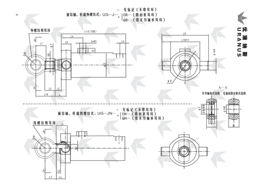
Tipo de eje frontal UG…J
Diámetro del cilindro |
Diámetro de la varilla |
∅1 |
∅2 |
∅3 |
∅7 |
L (LL) |
L1 |
El 2 |
L3 |
El número de |
L5 |
L6 |
L7 |
L8 |
L9 |
L10 (f11) |
L16 |
Barra |
B |
B1 |
H |
El número de unidades |
M2 |
Extremo de vástago tipo pendiente |
|||||
Dimensiones |
Tolerancia del agujero del rodamiento |
Sin amortiguación |
Amortiguación Y |
Cr |
Qr |
Ch |
QH |
||||||||||||||||||||||
40 |
20 |
20 |
0-0.010 |
58 |
70 |
25 |
30 (24) |
167 |
16 |
25 |
70 |
59 |
17 |
10 |
30 |
28 |
110 |
70 |
50 |
25 |
16 |
12 |
M18×1.5 |
M14×1.5 |
40-1 |
||||
22 |
28 |
M16×1.5 |
-2 |
||||||||||||||||||||||||||
28 |
35 |
M22×1.5 |
-3 |
||||||||||||||||||||||||||
50 |
25 |
30 |
70 |
80 |
28 |
35 (27) |
170 |
18 |
30 |
58 |
20 |
40 |
34 |
130 |
80 |
60 |
35 |
22 |
M20×1.5 |
50-1 |
|||||||||
28 |
35 |
M22×1.5 |
-2 |
||||||||||||||||||||||||||
36 |
42 |
M27×2 |
-3 |
||||||||||||||||||||||||||
63 |
32 |
83 |
100 |
35 |
37 (32) |
200 |
20 |
35 |
73 |
76 |
15 |
155 |
100 |
65 |
J5 |
M22×1.5 |
M24×1.5 |
63-1 |
|||||||||||
36 |
42 |
M27×2 |
-2 |
||||||||||||||||||||||||||
45 |
45 |
M33×2 |
-3 |
||||||||||||||||||||||||||
80 |
40 |
40 |
0-0.012 |
108 |
120 |
42 |
42 (40) |
217 |
45 |
75 |
25 |
18 |
55 |
44 |
185 |
125 |
105 |
45 |
28 |
M30×2 |
80-1 |
||||||||
45 |
48 |
M33×2 |
-2 |
||||||||||||||||||||||||||
56 |
60 |
M42×2 |
-3 |
||||||||||||||||||||||||||
90 |
45 |
114 |
135 |
48 |
78 |
200 |
140 |
110 |
M33×2 |
90-1 |
|||||||||||||||||||
50 |
52 |
M36×2 |
-2 |
||||||||||||||||||||||||||
63 |
68 |
M48×2 |
-3 |
||||||||||||||||||||||||||
100 |
50 |
50 |
127 |
150 |
52 |
47 (45) |
252 |
50 |
89 |
85 |
30 |
70 |
54 |
230 |
155 |
130 |
60 |
35 |
20 |
M27×2 |
M36×2 |
100-1 |
|||||||
56 |
60 |
M42×2 |
-2 |
||||||||||||||||||||||||||
70 |
72 |
M52×2 |
-3 |
||||||||||||||||||||||||||
110 |
56 |
140 |
165 |
60 |
257 |
55 |
90 |
90 |
245 |
170 |
135 |
M42×2 |
110-1 |
||||||||||||||||
63 |
68 |
M48×2 |
-2 |
||||||||||||||||||||||||||
80 |
80 |
M60×2 |
-3 |
||||||||||||||||||||||||||
125 |
63 |
152 |
185 |
68 |
267 |
60 |
104 |
87 |
35 |
260 |
185 |
140 |
M48×2 |
125-1 |
|||||||||||||||
70 |
72 |
M52×2 |
-2 |
||||||||||||||||||||||||||
90 |
90 |
M68×2 |
-3 |
||||||||||||||||||||||||||
140 |
70 |
60 |
0-0.015 |
168 |
210 |
72 |
52 (50) |
292 |
65 |
114 |
105 |
80 |
64 |
290 |
200 |
155 |
70 |
44 |
M33×2 |
M52×2 |
145-1 |
||||||||
80 |
80 |
M60×2 |
-2 |
||||||||||||||||||||||||||
100 |
100 |
M76×3 |
-3 |
||||||||||||||||||||||||||
150 |
75 |
180 |
222 |
76 |
297 |
70 |
119 |
110 |
305 |
215 |
157 |
M56×2 |
150-1 |
||||||||||||||||
85 |
85 |
M64×2 |
-2 |
||||||||||||||||||||||||||
105 |
105 |
M80×3 |
-3 |
||||||||||||||||||||||||||
160 |
80 |
194 |
235 |
80 |
302 |
75 |
124 |
115 |
320 |
230 |
160 |
M60×2 |
160-1 |
||||||||||||||||
90 |
90 |
M68×2 |
-2 |
||||||||||||||||||||||||||
110 |
110 |
M85×3 |
-3 |
||||||||||||||||||||||||||
180 |
90 |
70 |
219 |
270 |
90 |
62 (59) |
343 |
25 |
85 |
129 |
122 |
40 |
22 |
90 |
74 |
360 |
255 |
180 |
80 |
49 |
M42×2 |
M68×2 |
180-1 |
||||||
100 |
100 |
M76×3 |
-2 |
||||||||||||||||||||||||||
125 |
120 |
M95×3 |
-3 |
||||||||||||||||||||||||||
200 |
100 |
80 |
245 |
295 |
100 |
67 (64) |
353 |
95 |
141 |
127 |
100 |
84 |
405 |
285 |
200 |
90 |
55 |
M76×3 |
200-1 |
||||||||||
110 |
110 |
M85×3 |
-2 |
||||||||||||||||||||||||||
140 |
125 |
M100×3 |
-3 |
||||||||||||||||||||||||||
220 |
110 |
90 |
0-0.020 |
272 |
330 |
110 |
72 (65) |
393 |
105 |
146 |
143 |
50 |
110 |
94 |
455 |
320 |
225 |
100 |
60 |
25 |
M48×2 |
M85×3 |
220-1 |
||||||
125 |
120 |
M95×3 |
-2 |
||||||||||||||||||||||||||
160 |
140 |
M125×3 |
-3 |
||||||||||||||||||||||||||
250 |
125 |
100 |
299 |
355 |
120 |
76 (73) |
403 |
115 |
155 |
120 |
102 |
500 |
350 |
245 |
110 |
70 |
M95×3 |
250-1 |
|||||||||||
140 |
125 |
M100×3 |
-2 |
||||||||||||||||||||||||||
180 |
160 |
M145×3 |
-3 |
||||||||||||||||||||||||||
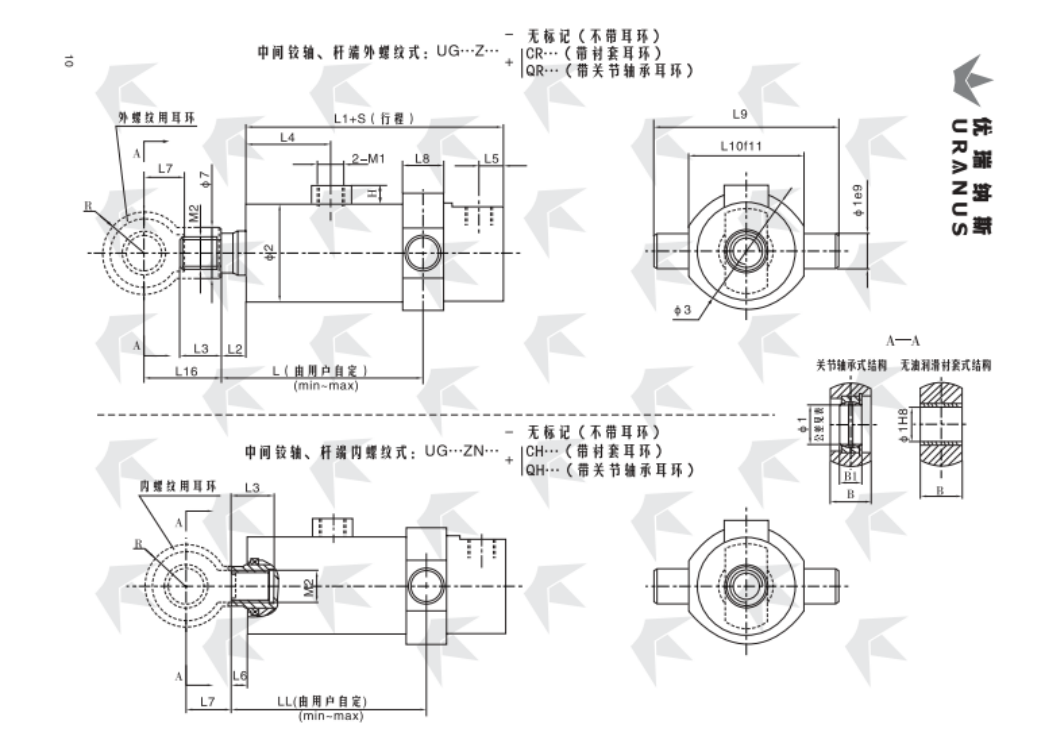
Eje intermedio de bisagra tipo UG…Z
Diámetro del cilindro |
Diámetro de la varilla |
∅1 |
∅2 |
∅3 |
∅7 |
L (LL) |
El |
El 2 |
L3 |
El número de |
L5 |
L6 |
L7 |
L8 |
L9 |
L10 (f11) |
L16 |
Barra |
B |
B1 |
H |
El número de unidades |
M2 |
Extremo de vástago tipo pendiente |
||||||
Dimensiones |
Tolerancia del agujero del rodamiento |
mínimo |
máx. |
Sin amortiguación |
Amortiguación Y |
Cr |
Qr |
Ch |
QH |
|||||||||||||||||||||
40 |
20 |
20 |
0-0.010 |
58 |
70 |
25 |
124 (118) |
113+S (107+S) |
167 |
16 |
25 |
70 |
59 |
17 |
10 |
30 |
28 |
110 |
70 |
50 |
25 |
16 |
12 |
M18×1.5 |
M14×1.5 |
40-1 |
||||
22 |
28 |
M16×1.5 |
-2 |
|||||||||||||||||||||||||||
28 |
35 |
M22×1.5 |
-3 |
|||||||||||||||||||||||||||
50 |
25 |
30 |
70 |
80 |
28 |
129 (121) |
112+S (104+S) |
170 |
18 |
30 |
58 |
20 |
15 |
40 |
34 |
130 |
80 |
60 |
35 |
22 |
M20×1.5 |
50-1 |
||||||||
28 |
35 |
M22×1.5 |
-2 |
|||||||||||||||||||||||||||
36 |
42 |
M27×2 |
-3 |
|||||||||||||||||||||||||||
63 |
32 |
83 |
100 |
35 |
143 (138) |
132+S (127+S) |
200 |
20 |
35 |
73 |
76 |
155 |
100 |
65 |
15 |
M22×1.5 |
M24×1.5 |
63-1 |
||||||||||||
36 |
42 |
M27×2 |
-2 |
|||||||||||||||||||||||||||
45 |
45 |
M33×2 |
-3 |
|||||||||||||||||||||||||||
80 |
40 |
40 |
0-0.012 |
108 |
120 |
42 |
142 (140) |
121+S (139+S) |
217 |
75 |
25 |
18 |
55 |
44 |
185 |
125 |
105 |
45 |
28 |
|||||||||||
M30×2 |
80-1 |
|||||||||||||||||||||||||||||
45 |
48 |
45 |
M33×2 |
-2 |
||||||||||||||||||||||||||
56 |
60 |
M42×2 |
-3 |
|||||||||||||||||||||||||||
90 |
45 |
114 |
135 |
48 |
147 (145) |
78 |
200 |
140 |
110 |
M33×2 |
90-1 |
|||||||||||||||||||
50 |
52 |
M36×2 |
-2 |
|||||||||||||||||||||||||||
63 |
68 |
M48×2 |
-3 |
|||||||||||||||||||||||||||
100 |
50 |
50 |
127 |
150 |
52 |
168 (166) |
149+S (147+S) |
252 |
50 |
89 |
85 |
30 |
70 |
54 |
230 |
155 |
130 |
60 |
35 |
20 |
M27×2 |
M36×2 |
100-1 |
|||||||
56 |
60 |
M42×2 |
-2 |
|||||||||||||||||||||||||||
70 |
72 |
M52×2 |
-3 |
|||||||||||||||||||||||||||
110 |
56 |
140 |
165 |
60 |
169 (167) |
153+S (151+S) |
257 |
55 |
90 |
90 |
245 |
170 |
135 |
M42×2 |
110-1 |
|||||||||||||||
63 |
68 |
M48 × 2 |
-2 |
|||||||||||||||||||||||||||
80 |
80 |
M60×2 |
-3 |
|||||||||||||||||||||||||||
125 |
63 |
152 |
185 |
68 |
183 (181) |
158+S (156+S) |
267 |
60 |
104 |
87 |
260 |
185 |
140 |
M48×2 |
125-1 |
|||||||||||||||
70 |
72 |
M52×2 |
-2 |
|||||||||||||||||||||||||||
90 |
90 |
M68×2 |
-3 |
|||||||||||||||||||||||||||
140 |
70 |
60 |
0-0.015 |
168 |
210 |
72 |
203 (201) |
175+S (173+S) |
292 |
65 |
114 |
105 |
35 |
80 |
64 |
290 |
200 |
155 |
70 |
44 |
M33×2 |
M52×2 |
140-1 |
|||||||
80 |
80 |
M60×2 |
-2 |
|||||||||||||||||||||||||||
100 |
100 |
M76×3 |
-3 |
|||||||||||||||||||||||||||
150 |
75 |
180 |
222 |
76 |
208 (206) |
177+S (175+S) |
297 |
70 |
119 |
110 |
305 |
215 |
157 |
M56×2 |
150-1 |
|||||||||||||||
85 |
85 |
M64×2 |
-2 |
|||||||||||||||||||||||||||
105 |
105 |
M80×3 |
-3 |
|||||||||||||||||||||||||||
160 |
80 |
194 |
235 |
80 |
213 (211) |
182+S (180+S) |
302 |
75 |
124 |
115 |
320 |
230 |
160 |
M60×2 |
160-1 |
|||||||||||||||
90 |
90 |
M68×2 |
-2 |
|||||||||||||||||||||||||||
110 |
110 |
M85×3 |
-3 |
|||||||||||||||||||||||||||
180 |
90 |
70 |
219 |
270 |
90 |
233 (230) |
205+S (202+S) |
343 |
25 |
85 |
129 |
122 |
40 |
22 |
90 |
74 |
360 |
255 |
180 |
80 |
49 |
M42×2 |
M68×2 |
180-1 |
||||||
100 |
100 |
M76×3 |
-2 |
|||||||||||||||||||||||||||
125 |
120 |
M95×3 |
-3 |
|||||||||||||||||||||||||||
200 |
100 |
80 |
245 |
295 |
100 |
250 (247) |
208+S (205+S) |
353 |
95 |
141 |
127 |
100 |
84 |
405 |
285 |
200 |
90 |
55 |
M76×3 |
200-1 |
||||||||||
110 |
110 |
M85×3 |
-2 |
|||||||||||||||||||||||||||
140 |
125 |
M100×3 |
-3 |
|||||||||||||||||||||||||||
220 |
110 |
90 |
0-0.020 |
272 |
330 |
110 |
262 (259) |
225+S (222+S) |
393 |
105 |
146 |
143 |
50 |
110 |
94 |
455 |
320 |
225 |
100 |
60 |
25 |
M48×2 |
M85×3 |
220-1 |
||||||
125 |
120 |
M95×3 |
-2 |
|||||||||||||||||||||||||||
160 |
140 |
M125×3 |
-3 |
|||||||||||||||||||||||||||
250 |
125 |
100 |
299 |
335 |
120 |
275 (272) |
226+S (223+S) |
403 |
115 |
155 |
120 |
102 |
500 |
350 |
245 |
110 |
70 |
M95×3 |
250-1 |
|||||||||||
140 |
125 |
M100×3 |
-2 |
|||||||||||||||||||||||||||
180 |
160 |
M145×3 |
-3 |
|||||||||||||||||||||||||||
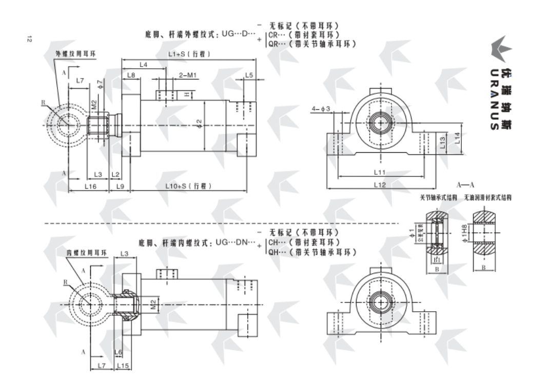
Tipo de pie UG…D
Diámetro del cilindro |
Diámetro de la varilla |
∅1 |
∅2 |
∅3 |
∅7 |
L1 |
El 2 |
L3 |
El número de |
L5 |
L6 |
L7 |
L8 |
L9 |
L10 |
L11 |
L12 |
L13 |
L14 |
L15 |
L16 |
Barra |
B |
B1 |
H |
El número de unidades |
M2 |
Extremo de vástago tipo pendiente |
|||||
Dimensiones |
Tolerancia del agujero del rodamiento |
Sin amortiguación |
Amortiguación Y |
Cr |
Qr |
Ch |
QH |
||||||||||||||||||||||||||
40 |
20 |
20 |
0-0.010 |
58 |
11 |
25 |
167 |
16 |
25 |
70 |
59 |
17 |
10 |
30 |
25 |
28.5 |
142 |
105 |
130 |
25 |
40 |
22.5 |
50 |
25 |
16 |
12 |
M18×1.5 |
M14×1.5 |
40-1 |
||||
22 |
28 |
M16×1.5 |
-2 |
||||||||||||||||||||||||||||||
28 |
35 |
M22×1.5 |
-3 |
||||||||||||||||||||||||||||||
50 |
25 |
30 |
70 |
28 |
170 |
18 |
30 |
58 |
20 |
40 |
30.5 |
145 |
120 |
150 |
30 |
45 |
22.5 |
60 |
35 |
22 |
M20×1.5 |
50-1 |
|||||||||||
28 |
35 |
M22×1.5 |
-2 |
||||||||||||||||||||||||||||||
36 |
42 |
M27×2 |
-3 |
||||||||||||||||||||||||||||||
63 |
32 |
83 |
13 |
35 |
200 |
20 |
35 |
73 |
76 |
15 |
30 |
35 |
170 |
140 |
175 |
35 |
50 |
30 |
65 |
15 |
M22×1.5 |
M24×1.5 |
63-1 |
||||||||||
36 |
42 |
M27×2 |
-2 |
||||||||||||||||||||||||||||||
45 |
45 |
M33×2 |
-3 |
||||||||||||||||||||||||||||||
80 |
40 |
40 |
0-0.012 |
108 |
17 |
42 |
217 |
45 |
75 |
25 |
18 |
55 |
40 |
40 |
177 |
160 |
200 |
40 |
60 |
38 |
105 |
45 |
28 |
M30×2 |
80-1 |
||||||||
45 |
48 |
M33×2 |
-2 |
||||||||||||||||||||||||||||||
56 |
60 |
M42×2 |
-3 |
||||||||||||||||||||||||||||||
90 |
45 |
114 |
48 |
78 |
185 |
230 |
45 |
70 |
110 |
M33×2 |
90-1 |
||||||||||||||||||||||
50 |
52 |
M36×2 |
-2 |
||||||||||||||||||||||||||||||
63 |
68 |
M48×2 |
-3 |
||||||||||||||||||||||||||||||
100 |
50 |
50 |
127 |
21 |
52 |
252 |
50 |
89 |
85 |
30 |
70 |
45 |
42.5 |
207 |
205 |
255 |
50 |
80 |
40.5 |
130 |
60 |
35 |
20 |
M27×2 |
M36×2 |
100-1 |
|||||||
56 |
60 |
M42×2 |
-2 |
||||||||||||||||||||||||||||||
70 |
72 |
M52×2 |
-3 |
||||||||||||||||||||||||||||||
110 |
56 |
140 |
60 |
257 |
55 |
90 |
90 |
212 |
230 |
280 |
55 |
90 |
135 |
M42×2 |
110-1 |
||||||||||||||||||
63 |
68 |
M48×2 |
-2 |
||||||||||||||||||||||||||||||
80 |
80 |
M60×2 |
-3 |
||||||||||||||||||||||||||||||
125 |
63 |
152 |
25 |
68 |
267 |
60 |
104 |
87 |
55 |
47$ |
255 |
310 |
60 |
100 |
45.5 |
140 |
M48×2 |
125-1 |
|||||||||||||||
70 |
72 |
M52×2 |
-2 |
||||||||||||||||||||||||||||||
90 |
90 |
M68×2 |
-3 |
||||||||||||||||||||||||||||||
140 |
70 |
60 |
0-0.015 |
168 |
72 |
292 |
65 |
114 |
105 |
35 |
80 |
237 |
280 |
340 |
65 |
115 |
155 |
70 |
44 |
M33×2 |
M52×2 |
145-1 |
|||||||||||
80 |
80 |
M60×2 |
-2 |
||||||||||||||||||||||||||||||
100 |
100 |
M76×3 |
-3 |
||||||||||||||||||||||||||||||
150 |
75 |
180 |
76 |
297 |
70 |
119 |
110 |
60 |
50 |
295 |
355 |
67 |
120 |
48 |
157 |
M56×2 |
150-1 |
||||||||||||||||
85 |
85 |
M64×2 |
-2 |
||||||||||||||||||||||||||||||
105 |
105 |
M80×3 |
-3 |
||||||||||||||||||||||||||||||
160 |
80 |
194 |
31 |
80 |
302 |
75 |
124 |
115 |
65 |
52.5 |
310 |
375 |
70 |
130 |
50.5 |
160 |
M60×2 |
160-1 |
|||||||||||||||
90 |
90 |
M68×2 |
-2 |
||||||||||||||||||||||||||||||
110 |
110 |
M85×3 |
-3 |
||||||||||||||||||||||||||||||
180 |
90 |
70 |
219 |
90 |
343 |
25 |
85 |
129 |
122 |
40 |
22 |
90 |
70 |
60 |
273 |
345 |
415 |
75 |
145 |
57 |
180 |
80 |
49 |
M42×2 |
M68×2 |
180-1 |
|||||||
100 |
100 |
M76×3 |
-2 |
||||||||||||||||||||||||||||||
125 |
120 |
M95×3 |
-3 |
||||||||||||||||||||||||||||||
200 |
100 |
80 |
245 |
100 |
353 |
95 |
141 |
127 |
100 |
283 |
385 |
465 |
80 |
165 |
200 |
90 |
55 |
M76×3 |
200-1 |
||||||||||||||
110 |
110 |
M85×3 |
-2 |
||||||||||||||||||||||||||||||
140 |
125 |
M100×3 |
-3 |
||||||||||||||||||||||||||||||
220 |
110 |
90 |
0-0.020 |
272 |
37 |
110 |
393 |
105 |
146 |
143 |
50 |
110 |
87 |
68.5 |
306 |
435 |
525 |
90 |
185 |
65.5 |
225 |
100 |
60 |
25 |
M48×2 |
M85×3 |
220-1 |
||||||
125 |
120 |
M95×3 |
-2 |
||||||||||||||||||||||||||||||
160 |
140 |
M125×3 |
-3 |
||||||||||||||||||||||||||||||
250 |
125 |
100 |
299 |
45 |
120 |
403 |
115 |
155 |
120 |
92 |
71 |
311 |
495 |
595 |
100 |
205 |
68 |
245 |
110 |
70 |
M95×3 |
250-1 |
|||||||||||
140 |
125 |
M100×3 |
-2 |
||||||||||||||||||||||||||||||
180 |
160 |
M145×3 |
-3 |
||||||||||||||||||||||||||||||
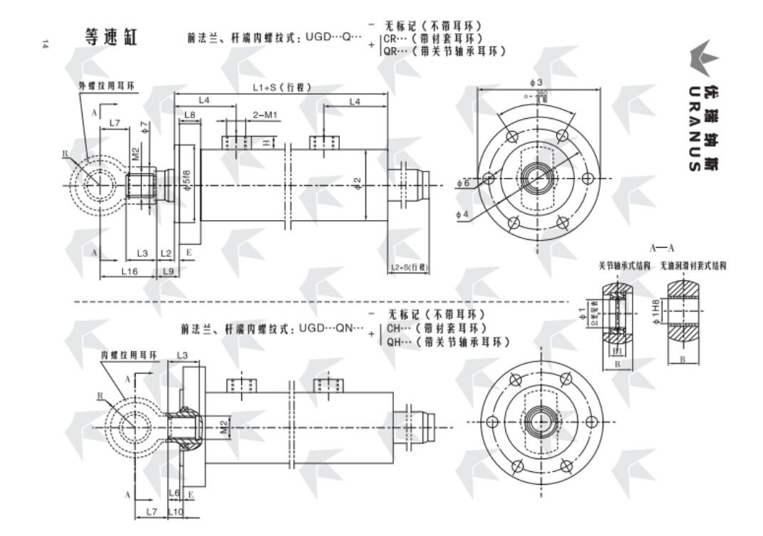
Cilindro de velocidad constante, tipo brida delantera UGD…D
Diámetro del cilindro |
Diámetro de la varilla |
∅1 |
∅2 |
∅3 |
∅4 |
∅5 f8 |
∅6 |
∅7 |
L1 |
El 2 |
L3 |
El número de |
L5 |
L6 |
L7 |
L8 |
L9 |
L10 |
L16 |
E |
Barra |
B |
B1 |
H |
El número de unidades |
M2 |
Extremo de vástago tipo pendiente |
|||||
Dimensiones |
Tolerancia del agujero del rodamiento |
Sin amortiguación |
Amortiguación Y |
Cr |
Qr |
Ch |
QH |
|||||||||||||||||||||||||
40 |
20 |
20 |
0-0.010 |
58 |
104 |
84 |
64 |
6 agujeros ∅ 11 |
25 |
192 |
16 |
25 |
70 |
59 |
17 |
10 |
30 |
20 |
21 |
15 |
50 |
5 |
25 |
16 |
12 |
M18×1.5 |
M14×1.5 |
40-1 |
||||
22 |
28 |
M16×1.5 |
-2 |
|||||||||||||||||||||||||||||
28 |
35 |
M22×1.5 |
-3 |
|||||||||||||||||||||||||||||
50 |
25 |
30 |
70 |
120 |
98 |
76 |
28 |
192 |
18 |
30 |
58 |
20 |
40 |
23 |
60 |
35 |
22 |
M20×1.5 |
50-1 |
|||||||||||||
28 |
35 |
M22×1.5 |
-2 |
|||||||||||||||||||||||||||||
36 |
42 |
M27×2 |
-3 |
|||||||||||||||||||||||||||||
63 |
32 |
83 |
140 |
115 |
90 |
6 agujeros ∅ 13 |
35 |
232 |
20 |
35 |
73 |
76 |
15 |
25 |
25 |
20 |
65 |
15 |
M22×1.5 |
M24×1.5 |
63-1 |
|||||||||||
36 |
42 |
M27×2 |
-2 |
|||||||||||||||||||||||||||||
45 |
45 |
M33×2 |
-3 |
|||||||||||||||||||||||||||||
80 |
40 |
40 |
0-0.012 |
108 |
175 |
145 |
115 |
8 agujeros ∅ 13.5 |
42 |
245 |
45 |
75 |
25 |
18 |
55 |
23 |
105 |
45 |
28 |
M30×2 |
80-1 |
|||||||||||
45 |
48 |
M33×2 |
-2 |
|||||||||||||||||||||||||||||
56 |
60 |
M42×2 |
-3 |
|||||||||||||||||||||||||||||
90 |
45 |
114 |
190 |
160 |
130 |
8 agujeros ∅ 15.5 |
48 |
78 |
110 |
M33×2 |
90-1 |
|||||||||||||||||||||
50 |
52 |
M36×2 |
-2 |
|||||||||||||||||||||||||||||
63 |
68 |
M48×2 |
-3 |
|||||||||||||||||||||||||||||
100 |
50 |
50 |
127 |
210 |
180 |
145 |
8 agujeros ∅ 18 |
52 |
275 |
50 |
89 |
85 |
30 |
70 |
30 |
130 |
60 |
35 |
20 |
M27×2 |
M36×2 |
100-1 |
||||||||||
56 |
60 |
M42×2 |
-2 |
|||||||||||||||||||||||||||||
70 |
72 |
M52×2 |
-3 |
|||||||||||||||||||||||||||||
110 |
56 |
140 |
225 |
195 |
160 |
60 |
285 |
55 |
90 |
90 |
135 |
M42×2 |
110-1 |
|||||||||||||||||||
63 |
68 |
M48×2 |
-2 |
|||||||||||||||||||||||||||||
80 |
80 |
M60×2 |
-3 |
|||||||||||||||||||||||||||||
125 |
63 |
152 |
240 |
210 |
175 |
10 Agujeros ∅ 18 |
68 |
298 |
60 |
104 |
87 |
40 |
140 |
M48×2 |
125-1 |
|||||||||||||||||
70 |
72 |
M52×2 |
-2 |
|||||||||||||||||||||||||||||
90 |
90 |
M68×2 |
-3 |
|||||||||||||||||||||||||||||
140 |
70 |
60 |
0-0.015 |
168 |
260 |
225 |
190 |
10 Agujeros ∅ 20 |
72 |
328 |
65 |
114 |
105 |
35 |
80 |
155 |
70 |
44 |
M33×2 |
M52×2 |
140-1 |
|||||||||||
80 |
80 |
M60×2 |
-2 |
|||||||||||||||||||||||||||||
100 |
100 |
M76×3 |
-3 |
|||||||||||||||||||||||||||||
150 |
75 |
180 |
285 |
245 |
205 |
10 Agujeros ∅ 22 |
76 |
333 |
70 |
119 |
110 |
157 |
M56×2 |
150-1 |
||||||||||||||||||
85 |
85 |
M64×2 |
-2 |
|||||||||||||||||||||||||||||
105 |
105 |
M80×3 |
-3 |
|||||||||||||||||||||||||||||
160 |
80 |
194 |
300 |
260 |
220 |
80 |
343 |
75 |
124 |
115 |
50 |
30 |
28 |
160 |
10 |
M60×2 |
160-1 |
|||||||||||||||
90 |
90 |
M68×2 |
-2 |
|||||||||||||||||||||||||||||
110 |
110 |
M85×3 |
-3 |
|||||||||||||||||||||||||||||
180 |
90 |
70 |
219 |
325 |
285 |
245 |
10 Agujeros ∅ 24 |
90 |
376 |
|
85 |
129 |
122 |
40 |
|
90 |
35 |
32 |
180 |
80 |
49 |
M42×2 |
M68×2 |
180-1 |
||||||||
100 |
100 |
M76×3 |
-2 |
|||||||||||||||||||||||||||||
125 |
120 |
M95×3 |
-3 |
|||||||||||||||||||||||||||||
200 |
100 |
80 |
245 |
365 |
320 |
275 |
10 Agujeros ∅ 26 |
100 |
396 |
95 |
141 |
127 |
100 |
60 |
200 |
90 |
55 |
M76×3 |
200-1 |
|||||||||||||
110 |
110 |
M85×3 |
-2 |
|||||||||||||||||||||||||||||
140 |
125 |
M100×3 |
-3 |
|||||||||||||||||||||||||||||
220 |
110 |
90 |
0-0.020 |
272 |
405 |
355 |
305 |
10 Agujeros ∅ 29 |
110 |
436 |
|
105 |
146 |
143 |
50 |
|
110 |
70 |
225 |
100 |
60 |
25 |
M48×2 |
M85×3 |
220-1 |
|||||||
125 |
120 |
M95×3 |
-2 |
|||||||||||||||||||||||||||||
160 |
140 |
M125×3 |
-3 |
|||||||||||||||||||||||||||||
250 |
125 |
100 |
299 |
450 |
390 |
330 |
12 Agujeros ∅ 32 |
120 |
446 |
115 |
155 |
120 |
245 |
110 |
70 |
M95×3 |
250-1 |
|||||||||||||||
140 |
125 |
M100×3 |
-2 |
|||||||||||||||||||||||||||||
180 |
160 |
M145×3 |
-3 |
|||||||||||||||||||||||||||||
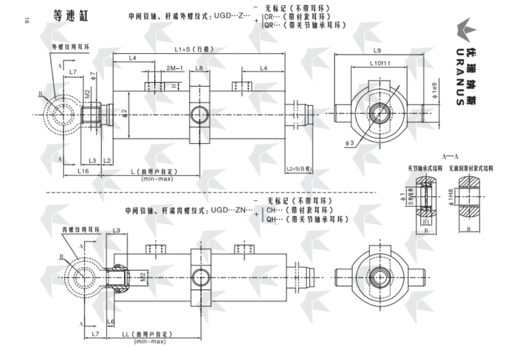
Eje intermedio UGD…Z del tipo de cilindro de velocidad constante
Diámetro del cilindro |
Diámetro de la varilla |
∅1 |
∅2 |
∅3 |
∅7 |
L (LL) |
L1 |
El 2 |
L3 |
El número de |
L6 |
L7 |
L8 |
L9 |
L10 (f11) |
L16 |
Barra |
B |
B1 |
H |
El número de unidades |
M2 |
Extremo de vástago tipo pendiente |
||||||
Dimensiones |
Tolerancia del agujero del rodamiento |
mínimo |
máx. |
Sin amortiguación |
Amortiguación Y |
Cr |
Qr |
Ch |
QH |
||||||||||||||||||||
40 |
20 |
20 |
0-0.010 |
58 |
70 |
25 |
124 (118) |
100+S (94+S) |
192 |
16 |
25 |
70 |
59 |
10 |
30 |
28 |
110 |
70 |
50 |
25 |
16 |
12 |
M18×1.5 |
M14×1.5 |
40-1 |
||||
22 |
28 |
M16×1.5 |
-2 |
||||||||||||||||||||||||||
28 |
35 |
M22×1.5 |
-3 |
||||||||||||||||||||||||||
50 |
25 |
30 |
70 |
80 |
28 |
129 (121) |
99+S (91+S) |
192 |
18 |
30 |
58 |
40 |
34 |
130 |
80 |
60 |
35 |
22 |
M20×1.5 |
50-1 |
|||||||||
28 |
35 |
M22×1.5 |
-2 |
||||||||||||||||||||||||||
36 |
42 |
M27×2 |
-3 |
||||||||||||||||||||||||||
63 |
32 |
83 |
100 |
35 |
143 (138) |
129+S (124+S) |
232 |
20 |
35 |
73 |
76 |
15 |
155 |
100 |
65 |
15 |
M22×1.5 |
M24×1.5 |
63-1 |
||||||||||
36 |
42 |
M27×2 |
-2 |
||||||||||||||||||||||||||
45 |
45 |
M33×2 |
-3 |
||||||||||||||||||||||||||
80 |
40 |
40 |
0-0.012 |
108 |
120 |
42 |
142 (140) |
143+S (141+S) |
245 |
45 |
75 |
18 |
55 |
44 |
185 |
125 |
105 |
45 |
28 |
M30×2 |
80-1 |
||||||||
45 |
48 |
M33×2 |
-2 |
||||||||||||||||||||||||||
56 |
60 |
M42×2 |
-3 |
||||||||||||||||||||||||||
90 |
45 |
114 |
135 |
48 |
147 (145) |
138+S (136+S) |
78 |
200 |
140 |
110 |
M33×2 |
90-1 |
|||||||||||||||||
50 |
52 |
M36×2 |
-2 |
||||||||||||||||||||||||||
63 |
68 |
M48×2 |
-3 |
||||||||||||||||||||||||||
100 |
50 |
50 |
127 |
150 |
52 |
168 (166) |
147+S (145+S) |
275 |
50 |
89 |
85 |
70 |
54 |
230 |
155 |
130 |
60 |
35 |
20 |
M27×2 |
M36×2 |
100-1 |
|||||||
56 |
60 |
M42×2 |
-2 |
||||||||||||||||||||||||||
70 |
72 |
M52×2 |
-3 |
||||||||||||||||||||||||||
110 |
56 |
140 |
165 |
60 |
169 (167) |
156+S (154+S) |
285 |
55 |
90 |
90 |
245 |
170 |
135 |
M42×2 |
110-1 |
||||||||||||||
63 |
68 |
M48×2 |
-2 |
||||||||||||||||||||||||||
80 |
80 |
M60×2 |
-3 |
||||||||||||||||||||||||||
125 |
63 |
152 |
185 |
68 |
183 (181) |
155+S (153+S) |
298 |
60 |
104 |
87 |
260 |
185 |
140 |
M48×2 |
125-1 |
||||||||||||||
70 |
72 |
M52×2 |
-2 |
||||||||||||||||||||||||||
90 |
90 |
M68×2 |
-3 |
||||||||||||||||||||||||||
140 |
70 |
60 |
0-0.015 |
168 |
210 |
72 |
203 (201) |
165+S (163+S) |
328 |
65 |
114 |
105 |
80 |
64 |
290 |
200 |
155 |
70 |
44 |
M33×2 |
M52×2 |
140-1 |
|||||||
80 |
80 |
M60×2 |
-2 |
||||||||||||||||||||||||||
100 |
100 |
M76×3 |
-3 |
||||||||||||||||||||||||||
150 |
75 |
180 |
222 |
76 |
208 (206) |
165+S (163+S) |
333 |
70 |
119 |
110 |
305 |
215 |
157 |
M56×2 |
150-1 |
||||||||||||||
85 |
85 |
M64×2 |
-2 |
||||||||||||||||||||||||||
105 |
105 |
M80×3 |
-3 |
||||||||||||||||||||||||||
160 |
80 |
194 |
235 |
80 |
213 (211) |
170+S (168+S) |
343 |
75 |
124 |
115 |
320 |
230 |
160 |
M60×2 |
160-1 |
||||||||||||||
90 |
90 |
M68×2 |
-2 |
||||||||||||||||||||||||||
110 |
110 |
M85×3 |
-3 |
||||||||||||||||||||||||||
180 |
90 |
70 |
219 |
270 |
90 |
233 (230) |
193+S (190+S) |
376 |
25 |
85 |
129 |
122 |
22 |
90 |
74 |
360 |
255 |
180 |
80 |
49 |
M42×2 |
M68×2 |
180-1 |
||||||
100 |
100 |
M76×3 |
-2 |
||||||||||||||||||||||||||
125 |
120 |
M95×3 |
-3 |
||||||||||||||||||||||||||
200 |
100 |
80 |
245 |
295 |
100 |
250 (247) |
196+S (193+S) |
396 |
95 |
141 |
127 |
100 |
84 |
405 |
285 |
200 |
90 |
55 |
M76×3 |
200-1 |
|||||||||
110 |
110 |
M85×3 |
-2 |
||||||||||||||||||||||||||
140 |
125 |
M100×3 |
-3 |
||||||||||||||||||||||||||
220 |
110 |
90 |
0-0.020 |
272 |
330 |
110 |
262 (259) |
224+S (221+S) |
436 |
105 |
146 |
143 |
110 |
94 |
455 |
320 |
225 |
100 |
60 |
25 |
M48×2 |
M85×3 |
220-1 |
||||||
125 |
120 |
M95×3 |
-2 |
||||||||||||||||||||||||||
160 |
140 |
M125×3 |
-3 |
||||||||||||||||||||||||||
250 |
125 |
100 |
299 |
335 |
120 |
275 (272) |
221+S (218+S) |
446 |
115 |
155 |
120 |
102 |
500 |
350 |
245 |
110 |
70 |
M95×3 |
250-1 |
||||||||||
140 |
125 |
M100×3 |
-2 |
||||||||||||||||||||||||||
180 |
160 |
M145×3 |
-3 |
||||||||||||||||||||||||||
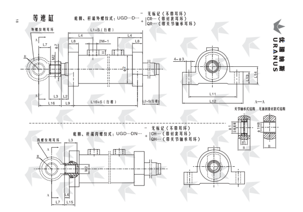
UGD…D tipo de pie cilindro de velocidad constante
Diámetro del cilindro |
Diámetro de la varilla |
∅1 |
∅2 |
∅3 |
∅7 |
L1 |
El 2 |
L3 |
El número de |
L5 |
L6 |
L7 |
L8 |
L9 |
L10 |
L11 |
L12 |
L13 |
L14 |
L15 |
L16 |
Barra |
B |
B1 |
H |
El número de unidades |
M2 |
Extremo de vástago tipo pendiente |
|||||
Dimensiones |
Tolerancia del agujero del rodamiento |
Sin amortiguación |
Amortiguación Y |
Cr |
Qr |
Ch |
QH |
||||||||||||||||||||||||||
40 |
20 |
20 |
0-0.010 |
58 |
11 |
25 |
192 |
16 |
25 |
70 |
59 |
17 |
10 |
30 |
25 |
28.5 |
167 |
105 |
130 |
25 |
40 |
22.5 |
50 |
25 |
16 |
12 |
M18×1.5 |
M14×1.5 |
40-1 |
||||
22 |
28 |
M16×1.5 |
-2 |
||||||||||||||||||||||||||||||
28 |
35 |
M22×1.5 |
-3 |
||||||||||||||||||||||||||||||
50 |
25 |
30 |
70 |
28 |
192 |
18 |
30 |
58 |
20 |
40 |
30.5 |
167 |
120 |
150 |
30 |
45 |
22.5 |
60 |
35 |
22 |
M20×1.5 |
50-1 |
|||||||||||
28 |
35 |
M22×1.5 |
-2 |
||||||||||||||||||||||||||||||
36 |
42 |
M27×2 |
-3 |
||||||||||||||||||||||||||||||
63 |
32 |
83 |
13 |
35 |
232 |
20 |
35 |
73 |
76 |
15 |
30 |
35 |
202 |
140 |
175 |
35 |
50 |
30 |
65 |
15 |
M22×1.5 |
M24×1.5 |
63-1 |
||||||||||
36 |
42 |
M27×2 |
-2 |
||||||||||||||||||||||||||||||
45 |
45 |
M33×2 |
-3 |
||||||||||||||||||||||||||||||
80 |
40 |
40 |
0-0.012 |
108 |
17 |
42 |
245 |
45 |
75 |
25 |
18 |
55 |
40 |
40 |
205 |
160 |
200 |
40 |
60 |
38 |
105 |
45 |
28 |
M30×2 |
80-1 |
||||||||
45 |
48 |
M33×2 |
-2 |
||||||||||||||||||||||||||||||
56 |
60 |
M42×2 |
-3 |
||||||||||||||||||||||||||||||
90 |
45 |
114 |
48 |
78 |
185 |
230 |
45 |
70 |
110 |
M33×2 |
90-1 |
||||||||||||||||||||||
50 |
52 |
M36×2 |
-2 |
||||||||||||||||||||||||||||||
63 |
68 |
M48×2 |
-3 |
||||||||||||||||||||||||||||||
100 |
50 |
50 |
127 |
21 |
52 |
275 |
50 |
89 |
85 |
30 |
70 |
45 |
42.5 |
230 |
205 |
255 |
50 |
80 |
40.5 |
130 |
60 |
35 |
20 |
M27×2 |
M36×2 |
100-1 |
|||||||
56 |
60 |
M42×2 |
-2 |
||||||||||||||||||||||||||||||
70 |
72 |
M52×2 |
-3 |
||||||||||||||||||||||||||||||
110 |
56 |
140 |
60 |
285 |
55 |
90 |
90 |
240 |
230 |
280 |
55 |
90 |
135 |
M42×2 |
110-1 |
||||||||||||||||||
63 |
68 |
M48×2 |
-2 |
||||||||||||||||||||||||||||||
80 |
80 |
M60×2 |
-3 |
||||||||||||||||||||||||||||||
125 |
63 |
152 |
25 |
68 |
298 |
60 |
104 |
87 |
55 |
47.5 |
243 |
255 |
310 |
60 |
100 |
45.5 |
140 |
M48×2 |
125-1 |
||||||||||||||
70 |
72 |
M52×2 |
-2 |
||||||||||||||||||||||||||||||
90 |
90 |
M68×2 |
-3 |
||||||||||||||||||||||||||||||
140 |
70 |
60 |
0-0.015 |
168 |
72 |
328 |
65 |
114 |
105 |
35 |
80 |
273 |
280 |
340 |
65 |
115 |
155 |
70 |
44 |
|
M52×2 |
145-1 |
|||||||||||
80 |
80 |
M60×2 |
-2 |
||||||||||||||||||||||||||||||
100 |
100 |
M33×2 |
M76×3 |
-3 |
|||||||||||||||||||||||||||||
150 |
75 |
180 |
76 |
333 |
70 |
119 |
110 |
60 |
50 |
295 |
355 |
67 |
120 |
48 |
157 |
M56×2 |
150-1 |
||||||||||||||||
85 |
85 |
M64×2 |
-2 |
||||||||||||||||||||||||||||||
105 |
105 |
M80×3 |
-3 |
||||||||||||||||||||||||||||||
160 |
80 |
194 |
31 |
80 |
343 |
75 |
124 |
115 |
65 |
52.5 |
278 |
310 |
375 |
70 |
130 |
50.5 |
160 |
M60×2 |
160-1 |
||||||||||||||
90 |
90 |
M68×2 |
-2 |
||||||||||||||||||||||||||||||
110 |
110 |
M85×3 |
-3 |
||||||||||||||||||||||||||||||
180 |
90 |
70 |
219 |
90 |
376 |
25 |
85 |
129 |
122 |
40 |
22 |
90 |
70 |
60 |
306 |
345 |
415 |
75 |
145 |
57 |
180 |
80 |
49 |
M42×2 |
M68×2 |
180-1 |
|||||||
100 |
100 |
M76×3 |
-2 |
||||||||||||||||||||||||||||||
125 |
120 |
M95×3 |
-3 |
||||||||||||||||||||||||||||||
200 |
100 |
80 |
245 |
100 |
396 |
95 |
141 |
127 |
100 |
326 |
385 |
465 |
80 |
165 |
200 |
90 |
55 |
M76×3 |
200-1 |
||||||||||||||
110 |
110 |
M85×3 |
-2 |
||||||||||||||||||||||||||||||
140 |
125 |
M100×3 |
-3 |
||||||||||||||||||||||||||||||
220 |
110 |
90 |
0-0.020 |
272 |
37 |
110 |
436 |
105 |
146 |
143 |
50 |
110 |
87 |
68.5 |
349 |
435 |
525 |
90 |
185 |
65.5 |
225 |
100 |
60 |
25 |
M48×2 |
M85×3 |
220-1 |
||||||
125 |
120 |
M95×3 |
-2 |
||||||||||||||||||||||||||||||
160 |
140 |
M125×3 |
-3 |
||||||||||||||||||||||||||||||
250 |
125 |
100 |
299 |
45 |
120 |
446 |
115 |
155 |
120 |
92 |
71 |
354 |
495 |
595 |
100 |
205 |
68 |
245 |
110 |
70 |
M95×3 |
250-1 |
|||||||||||
140 |
125 |
M100×3 |
-2 |
||||||||||||||||||||||||||||||
180 |
160 |
M145×3 |
-3 |
||||||||||||||||||||||||||||||


Derechos de autor © 2024 por Tianjin Uranus Hydraulic Machinery Co., Ltd.