
 EN
EN
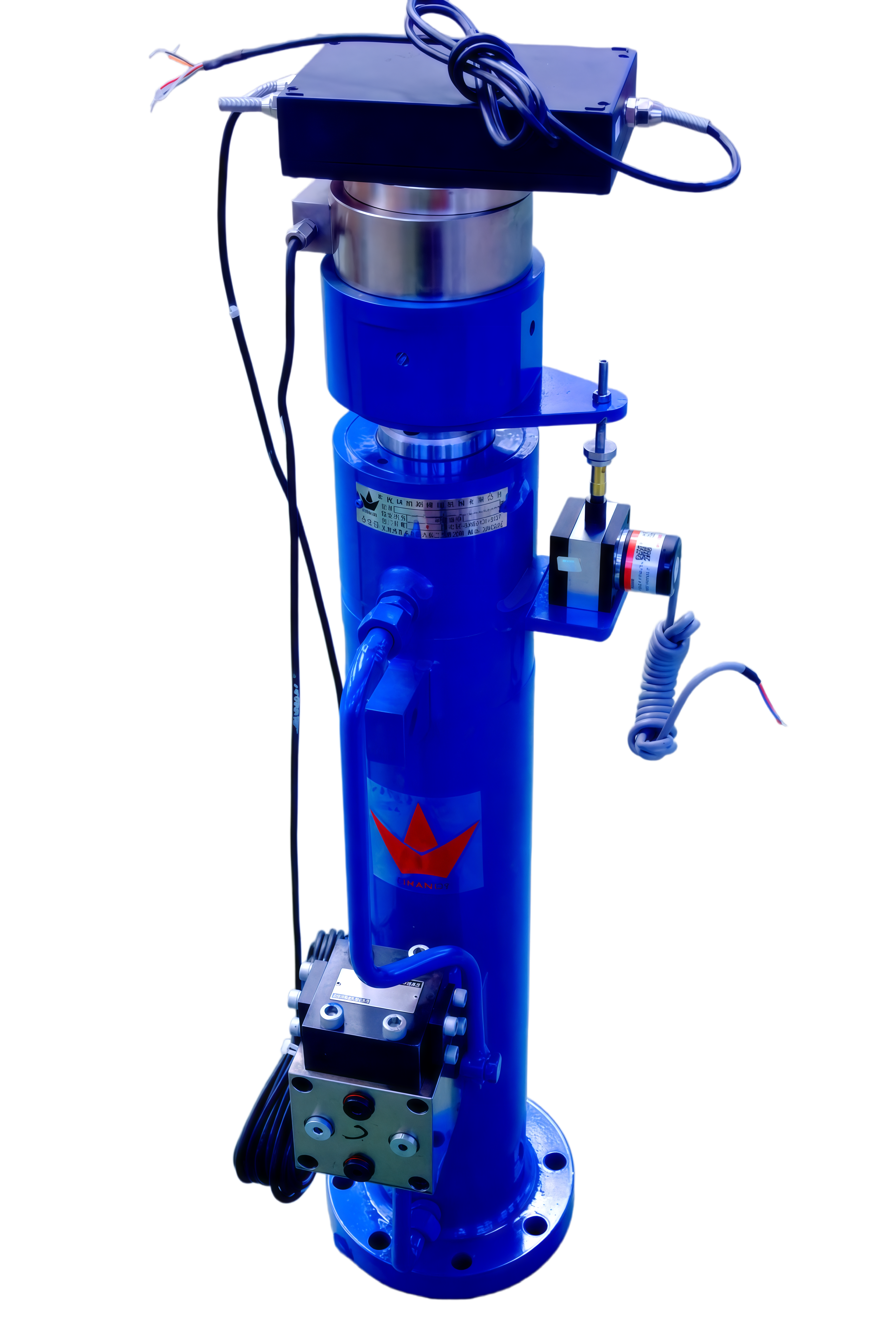
Synchronous Hydraulic Lifting Guide: Eight-Cylinder Precision, Control Strategies, and System Design
Introduction: Why Precision Matters in Multi-Cylinder Lifting
When lifting heavy structures—bridge girders, industrial presses, or massive steel frameworks—synchronous hydraulic lifting is the critical technology that ensures safety, stability, and structural integrity. Unlike single-cylinder applications, eight-cylinder synchronization demands far more than equal flow division.
Each cylinder encounters unique friction, seal drag, and minor load imbalances—factors that compound over the stroke and cause individual cylinders to lead or lag. When lifting rigid or sensitive structures, deviations exceeding 1 mm can induce dangerous tilting or structural stress. True millimeter-level synchronization requires continuous real-time position feedback and dynamic flow correction—not just steady-state flow matching.
This guide covers the core principles, architectural trade-offs, and practical system design considerations for synchronous hydraulic lifting with eight cylinders, including real-world performance data and best practices. [Internal Link: Explore our synchronous hydraulic lifting solutions]
1. Core Principles: Beyond Equal Flow Division
Why Eight-Cylinder Synchronization Requires Precision Beyond Equal Flow
Equal flow division alone rarely guarantees precise eight-cylinder synchronization. Stroke sensors (typically magnetostrictive or linear potentiometers) feed data to a control loop that adjusts proportional flow-control valves within milliseconds, compensating for load shifts. Without this adaptive response, even factory-calibrated mechanical flow dividers cannot prevent drift under variable external forces.
Key factors affecting synchronization:
Cylinder friction variation – Each cylinder has unique seal drag
Load imbalance – Uneven weight distribution across lifting points
Temperature effects – Oil viscosity changes with temperature
Internal leakage – Varies between cylinders over time
Effective synchronization hinges on integrating closed-loop electronics with robust mechanical flow splitting.
2. Architectural Trade-offs: Three Fundamental Approaches
Designers choose among three fundamental architectures for synchronous hydraulic lifting:
| Architecture | How It Works | Precision | Advantages | Disadvantages |
|---|---|---|---|---|
| Split-flow | Gear- or spool-type divider-combiners mechanically apportion flow | ±1–2 mm | Simple, electronics-free | Pressure intensification if one outlet stalls; limited compensation |
| Synchronous (Closed-loop) | Central pump feeds manifold of proportional valves; PLC adjusts valve openings in real time | ±0.2 mm | Highest precision; adaptive to load changes | Requires sensors, cabling, software tuning |
| Pump-per-point | Dedicated variable-displacement servo pump per cylinder | ±0.1 mm | Excellent for high-force, low-speed | High cost (8 pumps and drives) |
Optimal Choice Depends On:
Required accuracy – Sub-millimeter demands closed-loop or pump-per-point
Load dynamics – Varying loads require adaptive control
Budget – Split-flow is most economical; pump-per-point is premium
3. UF Series Distributor: Flow Division and Compensation
The UF Series distributor integrates precision flow division and load-sensing compensation, enabling eight-cylinder synchronous hydraulic lifting where stroke deviations must stay below 0.5 mm.
Flow Divider Efficiency and Load Imbalance Tolerance
According to Parker Hannifin‘s 2023 test data, the UF Series achieves 92–96% volumetric efficiency under typical load variations. This means:
Even when the heaviest cylinder’s demand shifts by 30%
The lightest receives only a 2–4% volume deviation
This resilience stems from internal pressure-compensated spools: each automatically adjusts orifice size in response to load pressure, maintaining a constant pressure drop across the metering edge. As a result, flow remains nearly proportional regardless of external load disparities. The design eliminates on-site manual tuning and enables real-time self-correction—a critical advantage when lifting unevenly loaded structures such as bridge girders or industrial presses.
Internal Pressure-Compensated Orifice Design vs. External Shuttle Valves
| Feature | UF Series (Internal) | External Shuttle Valve |
|---|---|---|
| Leak points | 1 (minimized) | 8+ (multiple) |
| Response delay | < 10 ms | 20–50 ms |
| Phase lag reduction | Up to 40% better | Baseline |
| Maintenance | Simpler; fewer components | Complex; more failure points |
| Reliability | Higher in contaminated/thermal environments | Lower |
The UF Series embeds the pressure-compensated orifice directly inside the distributor body. This integration removes external pilot lines and shuttle valves, reducing potential leak points from eight to one. Immediate pressure-to-flow adjustment yields a faster, more stable correction loop—cutting phase lag between cylinders by up to 40%.
4. Real-World Synchronization Challenges
Case Study: 3.2 mm Stroke Deviation in Bridge Bearing Replacement
In a 2022 bridge bearing replacement, eight hydraulic cylinders lifted a 320-ton deck section using a split-flow distributor. Despite operating near rated efficiency, a cumulative stroke deviation of 3.2 mm emerged—exceeding the project’s 2 mm alignment tolerance and causing unintended load shifting on one bearing pad.
Root-cause analysis identified:
Uneven load distribution – Not all cylinders carried equal weight
Temperature-driven viscosity changes – Oil temperature varied across the system
Internal leakage – Flow divider leakage accumulated over time
Key takeaway: Even high-efficiency mechanical flow division—while necessary—is insufficient for sub-millimeter synchronization without real-time correction in dynamic multi-cylinder applications.
Evolving Best Practice: Hybrid Closed-Loop Feedback + Mechanical Compensation
That experience accelerated adoption of hybrid control:
Displacement sensors on each cylinder feed position data to a PLC-based motion controller
Proportional valves are continuously adjusted to correct deviations as they arise
Mechanical flow compensator (e.g., UF Series distributor) handles baseline equal flow division
This layered approach consistently limits stroke deviation to below 0.5 mm in eight-cylinder setups, meeting the 2023 industry benchmark for critical lifting. Integrating active feedback with robust mechanical compensation has become standard practice where safety margins and tight schedules demand sub-millimeter precision.
5. Scalable Hydraulic System Design for Eight-Cylinder Lifting
Pump Sizing, Pressure Drop, and Flow Margin Calculations
System design begins by calculating total flow demand—the sum of individual cylinder flows at synchronous speed. With a UF-8 distributor dividing flow equally, the pump must supply this total plus allowances:
| Parameter | Calculation | Typical Value |
|---|---|---|
| Total flow demand | Sum of cylinder flow rates | Varies by cylinder size |
| Internal leakage allowance | 5–8% of total flow | Adds 5–8% margin |
| Flow margin (viscosity shifts) | 10–15% over calculated demand | Ensures transient stability |
Pressure considerations:
Account for pressure drop across the distributor‘s internal orifices
Total system pressure must exceed the highest load-induced pressure on any cylinder plus this drop
Sizing steps:
Calculate individual cylinder flow requirements at target speed
Sum to get total flow demand
Add 5–8% for leakage and volumetric losses
Add 10–15% flow margin for viscosity shifts and uneven loading
Verify the pump’s rated pressure exceeds load pressure + system pressure drop
Ensuring the pump exceeds peak demand with this margin prevents cavitation and preserves synchronization during transients. This sizing method scales naturally: for larger arrays, recalculate total flow and verify each distributor section operates within its rated range.
6. Application Spotlight: Bridge Bearing Replacement
Bridge bearing replacement is one of the most demanding applications for synchronous hydraulic lifting. The process requires:
Extreme precision – Bearings must align within ±1 mm tolerances
Multiple lift points – Often 4, 8, or more cylinders
Unpredictable load distribution – Existing structures have unknown internal stresses
Why UF Series excels in this application:
Internal pressure compensation handles uneven load distribution
Real-time self-correction eliminates manual tuning
Reduced leak points improve reliability on critical infrastructure projects
Results from recent projects:
Stroke deviation consistently < 0.5 mm
Setup time reduced by 30% compared to external shuttle valve systems
Project completion accelerated with fewer delays [Internal Link: See our bridge lifting case studies]
7. Maintenance and Reliability Considerations
To maximize the lifespan and reliability of your synchronous hydraulic lifting system:
Regular oil analysis – Monitor contamination levels (target ISO 4406 code 18/16/13 or better)
Sensor calibration – Verify position sensors (magnetostrictive or LVDT) annually
Valve inspection – Check proportional valves and compensator spools for wear
Seal replacement – Follow manufacturer recommendations for cylinder seal intervals
Software updates – Keep PLC control algorithms current
Proactive maintenance reduces unplanned downtime and ensures sub-millimeter precision over the life of the equipment—critical for infrastructure projects where safety margins are non-negotiable.
FAQ
Why is equal flow division not enough for eight-cylinder synchronization?
Equal flow division does not account for unique factors like cylinder friction, seal drag, and uneven load distribution. Continuous real-time position feedback and dynamic flow correction are required to ensure millimeter-level synchronization.
What are the main architectural options for multi-cylinder hydraulic systems?
The primary options are split-flow systems, synchronous systems with closed-loop feedback, and pump-per-point configurations. Each varies in complexity, precision, and cost.
How does the UF Series Distributor address load imbalance?
The UF Series integrates internal pressure-compensated spools to adjust orifice sizes dynamically and maintain nearly proportional flow even under load shifts, reducing deviations.
What caused deviations in the case study of bridge bearing replacement?
Uneven load distribution, temperature-driven viscosity changes, and internal leakage led to a cumulative 3.2 mm stroke deviation. Real-time correction and hybrid closed-loop feedback systems can prevent such issues.
How is a pump sized for a system with a UF-8 distributor?
Pump sizing requires calculating total flow demand, adding allowances for leakage and losses, and including a margin of 10–15% to handle load dynamics and viscosity shifts.
What is the typical accuracy of a closed-loop synchronous hydraulic system?
Closed-loop systems with proportional valves and position feedback typically achieve ±0.2 mm stroke difference in eight-cylinder configurations, meeting most critical lifting requirements.
Conclusion: Invest in Precision for Safe, Efficient Lifting
Synchronous hydraulic lifting with eight cylinders is a complex but essential technology for heavy infrastructure and industrial applications. By understanding the core principles—beyond equal flow division—and selecting the right architecture (split-flow, closed-loop, or pump-per-point), you can achieve sub-millimeter precision, improve safety, and reduce project delays.
The UF Series distributor offers a proven solution for eight-cylinder synchronization, combining internal pressure compensation, reduced leak points, and reliable performance in challenging conditions. When integrated with closed-loop feedback, it consistently delivers stroke deviations below 0.5 mm.
Ready to discuss your synchronous hydraulic lifting project? [Contact our engineering team] for system design assistance, product specifications, and a free consultation.
[Internal Link: Browse our full range of hydraulic synchronization products]
Table of Contents
- Introduction: Why Precision Matters in Multi-Cylinder Lifting
- 1. Core Principles: Beyond Equal Flow Division
- 2. Architectural Trade-offs: Three Fundamental Approaches
- 3. UF Series Distributor: Flow Division and Compensation
- 4. Real-World Synchronization Challenges
- 5. Scalable Hydraulic System Design for Eight-Cylinder Lifting
- 6. Application Spotlight: Bridge Bearing Replacement
- 7. Maintenance and Reliability Considerations
- FAQ
- Conclusion: Invest in Precision for Safe, Efficient Lifting