홈페이지 > 제품 > 맞춤형 하이드라울릭 실린더


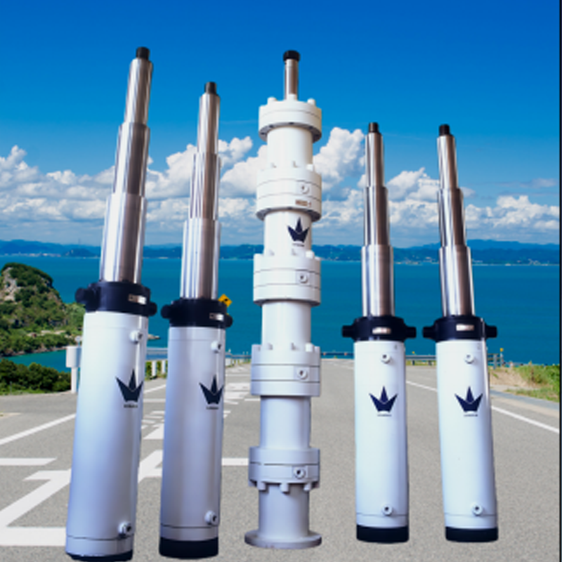
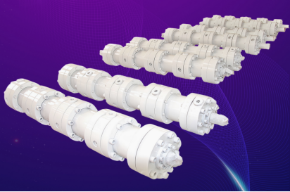
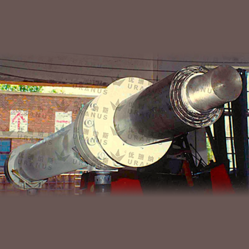
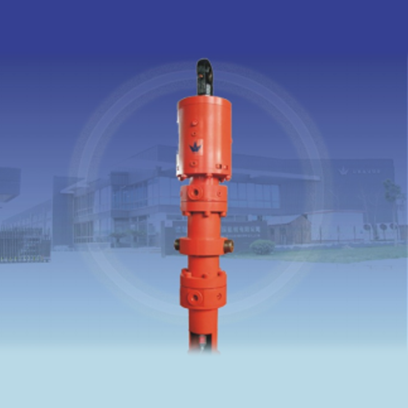
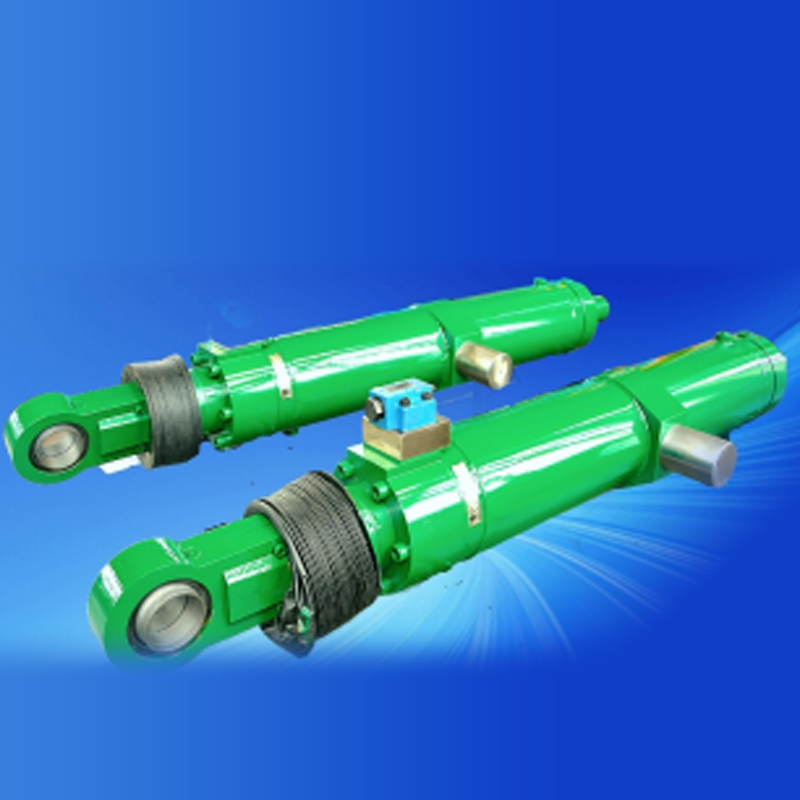
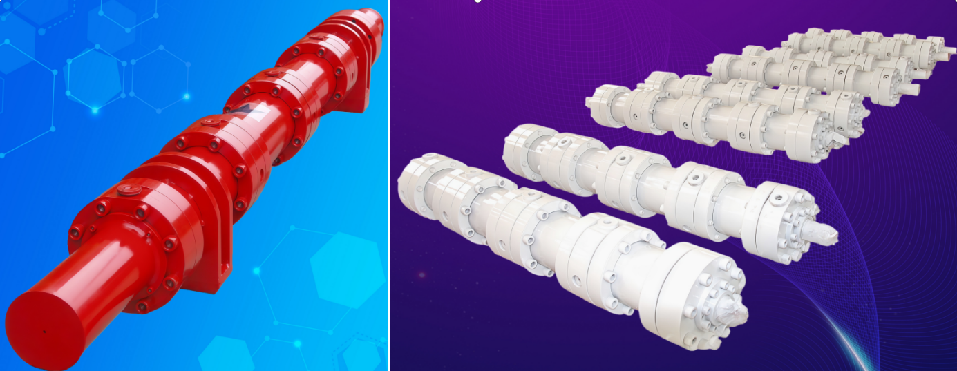
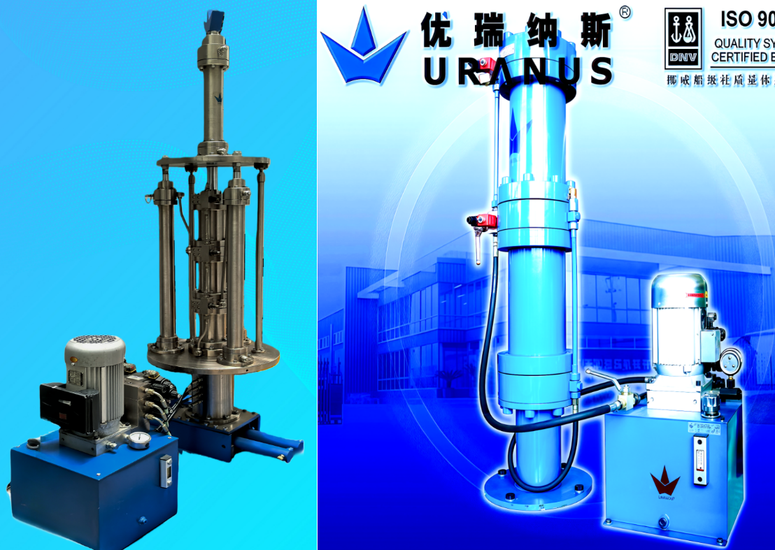
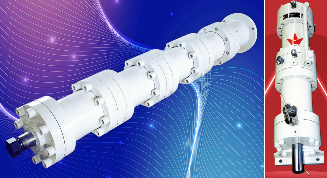
UF 시리즈 동기 분배기 유압 실린더 제품 사진 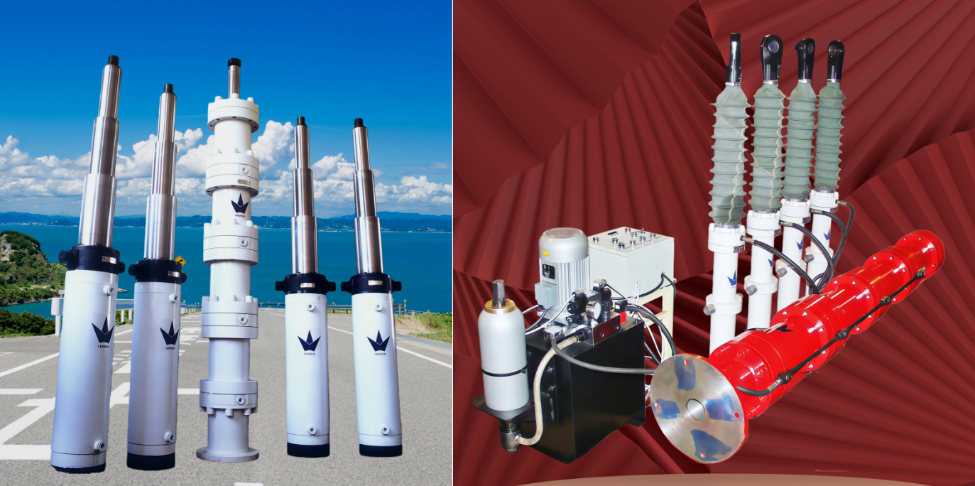

UF 시리즈 동기 분배기 유압 실린더 선택 및 사용 설명서
UF 시리즈 동기 분배기 유압 실린더(이하 UF 실린더라 함)는 URANUS가 개발한 신제품 시리즈 중 하나입니다.
UF 실린더는 단일로드 다중 피스톤 유압 실린더입니다. 구조도는 오른쪽에 표시되어 있습니다:
모든 피스톤이 단일 실린더 바렐과 단일 피스톤 로드를 공유하기 때문에, 이들의 원형 단면적은 동일하다. 피스톤이 움직일 때 모든 피스톤은 동일한 스트로크를 동일한 속도로 이동하므로, 입력 및 출력 양쪽의 압력 매체의 유량과 용적이 정확히 일치한다. UF 실린더의 가장 큰 장점은 그 동기화 정밀도가 시스템 압력, 유량, 부하 또는 기타 외부 요인에 영향을 받지 않는다는 점이다. 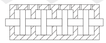
UF 실린더는 유럽과 미국에서 개발된 최첨단 내부 및 외부 누수 제로 씰 기술을 채택하고 있다. 거시적으로 볼 때, UF 실린더는 절대적인 동기화를 달성할 수 있으며, 이는 속도 제어 밸브, 동기화 밸브 또는 동기화 모터가 제공할 수 없는 능력이다.
UF 실린더는 동기화 오류가 없기 때문에 추적, 감지 또는 비교를 위한 다양한 변위 센서를 사용할 필요가 없으며, 고가의 서보 또는 비례 시스템도 필요하지 않습니다. 이로 인해 비용과 고장률, 유지보수 비용이 크게 줄어듭니다.
UF 실린더의 성능: 작동 압력: 0~25 MPa, 최소 작동 개시 압력: ≤0.3 MPa, 압력 시험: 32 MPa. 일반적인 UF 실린더는 다양한 광물성 오일을 작업 유체로 사용할 수 있습니다. 특수 UF 실린더는 물, 물-글리콜 혼합액, 유화액, 인산 에스터 및 각종 약산성 또는 약알칼리성 작업 유체를 사용할 수 있습니다. 작동 온도: 일반 UF 실린더: –35 °C ~ 80 °C, 고온용 UF 실린더: –35 °C ~ 220 °C. 작동 속도: 일반 UF 실린더: 500 mm/s, 고속 UF 실린더: 최대 2,000 mm/s 이상. 최대 출력 용량: 이중 피스톤 UF 실린더: 2 × 240 L, 4단 피스톤 UF 실린더: 4 × 120 L
UF 실린더는 다음 유형의 유압 실린더에 대해 동기화를 달성할 수 있습니다.
1. 플런저 직경과 스토로크가 동일한 단동식 플런저 실린더, 단동식 다단계 실린더 및 랙-피니언 회전 유압 실린더.
2. 피스톤 직경, 피스톤 로드 직경 및 스토로크가 동일한 복동식 유압 실린더 및 복동식 다단계 실린더.
3. 피스톤 직경과 스토로크는 동일하지만 피스톤 로드 직경이 다른 복동식 피스톤 실린더.
4. 복동식 피스톤 실린더의 직경과 스토로크가 단동식 플런저 실린더의 플런저 직경과 스토로크와 동일할 경우, 이 두 가지 서로 다른 유형의 유압 실린더도 동기 작동이 가능합니다.
5. 다양한 유형, 실린더 보어, 로드 직경, 스토로크, 하중 및 작동 압력이 다른 유압 실린더라도 그 부피가 동일하면 동시에 작동할 수 있습니다.
동일한 스트로크를 가지되 실린더 지름, 로드 지름 및 용적이 서로 다른 유압 실린더의 동기화 작동을 구현할 수 있는 UFT 비등용량 동기 분배 실린더도 제공 가능합니다. UFT 실린더는 고객 요구 사항에 따라 설계 및 제조되는 비표준 실린더입니다.
체크 밸브가 장착된 UF 실린더는 고정 배출량 인젝터로도 사용할 수 있습니다.
내장형 또는 외장형 변위 센서가 장착된 UF 실린더는 동기 실린더의 서보 제어 또는 비례 제어를 가능하게 합니다.
UF 실린더는 내부 누유량이 큰 동기 실린더에는 적합하지 않습니다.
당사는 동기 실린더와 동기 유압 어셈블리를 모두 포함하는 완전한 동기 유압 시스템도 제공할 수 있습니다.
당사의 동기식 유압 실린더는 유럽과 미국에서 수입한 고품질 씰을 사용하여 내부 및 외부 누유가 전혀 없을 뿐만 아니라 매우 긴 수명을 보장합니다. 일반적으로 고장 없이 작동 가능한 거리는 100만 미터에서 1천만 미터에 이릅니다.
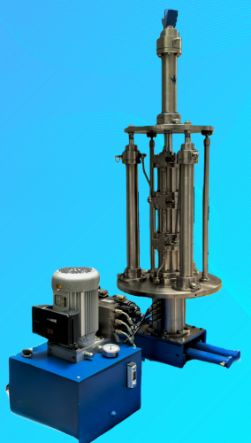
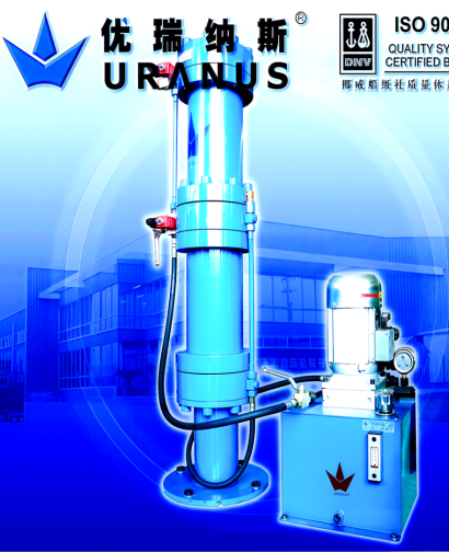
당사의 UZ 시리즈 동기식 유압 실린더 스테이션은 작동의 신뢰성은 물론 구조가 컴팩트하고 심미적인 디자인을 특징으로 합니다.
UF 실린더 선택 방법:
1. 먼저 동기식 실린더의 용량을 cm³ 단위로 계산한 후, UF 실린더의 링형 면적으로 나누어 UF 실린더의 스트로크를 결정합니다(5페이지 참조). 다음은 두 가지 예시입니다.
1.1 지름 80mm, 스트로크 1000mm인 플런저 실린더 또는 실린더 지름 80mm, 로드 지름 45mm, 스트로크 1000mm인 피스톤 실린더(로드 없는 측)의 용량은 다음과 같습니다: (80÷20)²π×(1000÷10)=1600πcm³
내경이 125mm인 UF 실린더를 선택하는 경우, UF 실린더의 스토로크는 다음과 같아야 합니다: 1600π÷32.81π×10≈488mm
내경이 140mm인 UF 실린더를 선택하는 경우, 스토로크는 다음과 같아야 합니다: 1600π÷39.08π×10≈409mm
실린더 지름이 100mm이고, 로드 지름이 70mm이며, 스트로크가 1000mm인 피스톤 실린더의 로드 측 챔버 용적은:
[(100÷20)²-(70÷20)²]π×(1000÷10)=1275πcm³
내경이 125mm인 UF 실린더를 선택하는 경우, UF 실린더의 스트로크는 다음과 같아야 합니다:
2. 용적 손실에 대한 보상: 계산 오차, 제조 공차 및 배관 내 용적 손실로 인한 용적 감소를 방지하기 위해 UF 실린더의 스트로크는 일반적으로 계산된 스트로크보다 3~20mm 더 길게 설계된다. 따라서 예제 1.1에서 UF125 실린더를 선택할 경우 스트로크를 495mm까지 증가시킬 수 있으며, UF140 실린더의 경우 스트로크를 415mm까지 증가시킬 수 있다. 예제 1.2에서는 UF125 실린더의 스트로크를 395mm까지 증가시킬 수 있다. UF 실린더의 실제 스트로크를 연장함으로써 스트로크 양끝에서의 충격을 방지하고 수명을 연장할 수 있다.
3. 스트로크 제한: UF 실린더는 직렬로 연결된 다수의 피스톤으로 구성되어 있으므로, UF 실린더의 스트로크(특히 여러 실린더를 동기화할 경우)가 너무 길어지지 않도록 해야 한다.
UF 실린더의 작동 원리:
동기화 실린더를 위한 동기화 시스템은 다양한 유형이 존재한다. 아래에서는 UF 실린더의 작동 원리를 설명하기 위해 흔히 사용되는 두 가지 간단한 예를 제시한다.
1. 4피스톤 동기 실린더의 유압 회로도 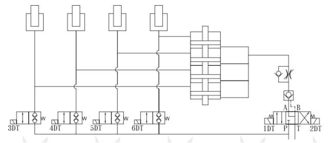
도면에서 1DT가 전원을 공급받으면, 3위치 4방향 솔레노이드 밸브가 방향을 전환하여 압력을 받은 오일이 UF 실린더의 네 개 하부 챔버로 유입되며, 네 개의 피스톤을 위쪽으로 밀어 올립니다. 그 후 작동 매체는 네 개의 플런저 실린더에 균등하게 공급되어 모든 플런저 실린더가 동기화되어 상승합니다. 솔레노이드 1DT의 전원이 차단되면 방향 제어 밸브가 원래 위치로 돌아가고, 플런저 실린더의 움직임이 정지합니다. 이때 UF 실린더 하부 챔버의 오일은 파일럿 조작 체크 밸브에 의해 잠겨, 플런저 실린더가 하강하는 것을 방지합니다. 2DT에 전원이 공급되면 방향 제어 밸브가 전환되어 파일럿 조작 체크 밸브가 열리게 되고, 하중에 의해 발생한 압력으로 인해 UF 실린더의 피스톤이 아래로 이동하며, 작동 매체는 스로틀 밸브를 통해 다시 오일 탱크로 흘러가 모든 네 개의 플런저 실린더가 동기화되어 하강하게 됩니다. 사고를 방지하기 위해 각 동기화 실린더에는 2위치 2방향 보충 오일 밸브가 장착되어 있으며, 이 밸브는 누유가 없는 종류여야 합니다. 이 밸브는 동기화 실린더의 스토크 끝 직전에 설치된 리미트 스위치 또는 근접 스위치에 의해 작동되며(정확한 거리는 요구되는 동기화 정밀도에 따라 결정됨), 예를 들어 동기화 정밀도가 2mm 이상이어야 하는 경우, 플런저 실린더 스토크 끝보다 1.5mm 앞에 리미트 스위치를 설치합니다.
일부 실린더가 스트로크 끝에 도달했을 때 다른 실린더들이 아직 리미트 스위치를 작동시키지 않은 경우, 시스템은 가청 및 시각 경보를 작동시키고 2방향 밸브의 솔레노이드에 전원을 공급하여 밸브를 전환시켜 압력 오일이 실린더로 직접 흐르도록 하여 모든 실린더가 스트로크 끝까지 도달하도록 보장합니다.
경보 신호가 발생하면 고장을 즉시 조치해야 합니다. 고장의 가능한 원인은 다음과 같습니다:
① 배관 또는 피팅에서 외부 누유. ② 동기화 실린더 내부 또는 외부 누유. ③ 보충 오일 밸브 내부 또는 외부 누유. ④ UF 실린더 내부 또는 외부 누유.
2. 4피스톤 동기화 실린더의 유압 회로도 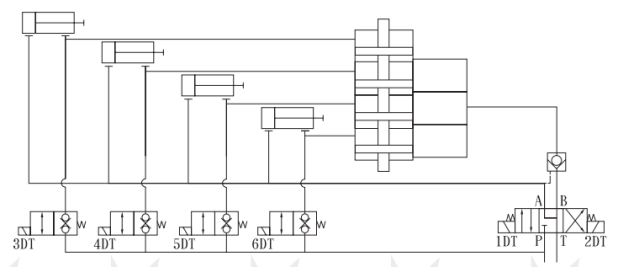
로드 챔버가 있거나 없는 피스톤 방식 동기 실린더는 모두 사용자의 재량에 따라 UF 실린더에 연결할 수 있습니다. 일반적으로는 UF 실린더를 부피가 작고 작동 압력이 낮은 챔버에 연결하는 것이 권장됩니다. 부피가 작을수록 UF 실린더의 비용이 낮아지고, 작동 압력이 낮을수록 고장 없는 서비스 수명이 길어집니다. 도면에서 1DT가 전원 인가되면 방향 제어 밸브가 전환되고 가압 오일이 UF 실린더의 하부 챔버로 유입되어 피스톤을 밀어내며, 상부 챔버의 오일을 동기 실린더의 로드 챔버로 이동시켜 피스톤 로드가 동기적으로 후퇴하게 됩니다. 1DT의 전원이 차단되면 방향 제어 밸브는 중립 위치로 돌아가며, 파일럿 조작 체크 밸브들이 모든 유압 실린더를 잠급니다. 2DT가 전원 인가되면 가압 오일이 동기 실린더의 로드리스 챔버로 유입되면서 동시에 파일럿 조작 체크 밸브들이 열립니다. 동기 실린더 피스톤의 움직임은 로드 챔버의 작동 유체를 UF 실린더의 상부 챔버로 이동시키며 피스톤을 아래로 밀어내어 네 개의 피스톤 로드가 모두 동기적으로 신장되게 합니다. 보충 오일 작동은 본질적으로 동기 플런저 실린더와 동일하지만, 리미트 스위치는 이제 피스톤 로드가 완전히 후퇴하기 직전 위치에 설치해야 합니다.
UF 실린더 설치: 공간을 절약하고 수명을 연장하기 위해 UF 실린더는 수직 설치를 위한 설계입니다. 플랜지 치수는 5페이지에 제공되어 있습니다. 플랜지의 장착 기초는 견고하고 신뢰성 있어야 합니다. 수평 설치가 반드시 필요한 경우, 실린더는 가능한 한 수평을 유지해야 하며, 길이가 길거나 무거운 UF 실린더는 추가 지지점이 필요하고 방향 전환으로 인한 이동이나 충격을 방지하기 위해 단단히 고정되어야 합니다. 수평으로 설치된 UF 실린더는 베이스 마운팅 플랜지를 포함하지 않지만, 고객 요청 시 마운팅 지지대를 제공할 수 있습니다.
UF 실린더 사용 시 주의사항: UF 실린더는 부피식 동기화 실린더이므로, 누유는 동기화 성능에 영향을 미칩니다. 따라서 다음의 주의사항을 준수해야 합니다.
1. UF 실린더, 동기화 실린더 및 배관 내부의 모든 공기를 완전히 제거해야 합니다.
2. 동기 실린더, 보충 오일 밸브, 배관 및 연결 부위는 누유가 없어야 합니다.
3. 작동 유체는 여과되어야 하며, 청정도 등급은 NAS1638 Class 9 또는 ISO4406:19/15 이상이어야 합니다.
4. 벤트 후 UF 실린더의 벤트 나사는 단단히 조여져야 합니다.
5. 작동 압력은 정격 압력을 초과해서는 안 됩니다.
6. 설치 기초는 견고하고 신뢰성 있어야 합니다.
7. 동기 오류 경보 발생 시 즉시 점검하고 조치를 취해야 합니다.
8. 장거리 고압 배관의 경우 열팽창 및 수축을 최대한 줄여야 합니다.
장기간 보관 시, UF 실린더는 부식 방지 오일로 채우고 오일 포트를 밀봉해야 합니다.
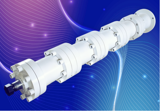
UF 시리즈 동기 분배형 유압 실린더 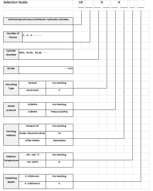
UF 시리즈 분배형 유압 실린더 전체 치수 및 설치 치수
실린더 지름 |
막대 지름 |
환형 면적 (cm ² ) |
L |
L1 |
1 2 |
φ 1 |
φ 2 |
φ 3 |
φ 4 |
φ 5 |
φ 6 |
B |
오일 포트 (M) |
80 |
40 |
12π |
154 |
50 |
104 |
180 |
210 |
17 |
108 |
152 |
50 |
16 |
M27 ×2 |
100 |
40 |
21π |
187 |
60 |
125 |
215 |
250 |
17 |
127 |
176 |
50 |
16 |
M33 ×2 |
125 |
50 |
32.81π |
227 |
65 |
145 |
260 |
300 |
17 |
159 |
220 |
60 |
16 |
M42 ×2 |
140 |
63 |
39.08π |
231 |
65 |
155 |
290 |
335 |
17 |
178 |
246 |
70 |
16 |
M42 ×2 |
160 |
70 |
51.75π |
242 |
70 |
176 |
330 |
380 |
17 |
194 |
272 |
80 |
16 |
M48 ×2 |
180 |
70 |
68.75π |
262 |
70 |
186 |
365 |
420 |
17 |
219 |
300 |
80 |
16 |
M48 ×2 |
200 |
90 |
79.75π |
262 |
75 |
196 |
400 |
460 |
22 |
245 |
330 |
100 |
20 |
M48 ×2 |
220 |
100 |
96π |
262 |
75 |
216 |
450 |
520 |
22 |
270 |
365 |
110 |
20 |
M48 ×2 |
250 |
110 |
126π |
296 |
80 |
236 |
500 |
570 |
22 |
299 |
410 |
120 |
20 |
M48 ×2 |
280 |
125 |
56.94π |
306 |
80 |
256 |
570 |
660 |
22 |
325 |
642 |
130 |
20 |
M48 ×2 |
320 |
140 |
207π |
326 |
80 |
256 |
650 |
750 |
22 |
375 |
525 |
150 |
20 |
M48 ×2 |
360 |
160 |
260π |
356 |
80 |
276 |
650 |
780 |
22 |
420 |
560 |
170 |
20 |
M48 ×2 |
400 |
160 |
336π |
406 |
80 |
276 |
730 |
820 |
22 |
470 |
625 |
170 |
20 |
M48 ×2 |
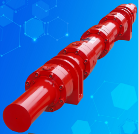
비등용량 동기 분배 유압 실린더
비등용량 동기 분배 유압 실린더의 동기화 원리는 UF 실린더와 동일하다. 이들은 모두 단일로드 다중 피스톤 유압 실린더로, 모든 피스톤이 동일한 스트로크와 속도를 갖는다. 각 피스톤의 크기는 고객이 요구하는 출력 용량에 따라 결정된다. 비등용량 동기 분배 유압 실린더가 필요할 경우, 원하는 용량(또는 동기 실린더의 실린더 보어, 로드 지름 및 스트로크), 수량, 작동 압력 및 기타 관련 매개변수를 제공하시기 바란다. 이 정보를 바탕으로 정확한 전체 치수와 기술 사양을 제공하며, 설계 및 제조 전에 귀하의 확인을 받아 최종 확정하게 된다.
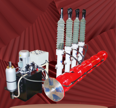
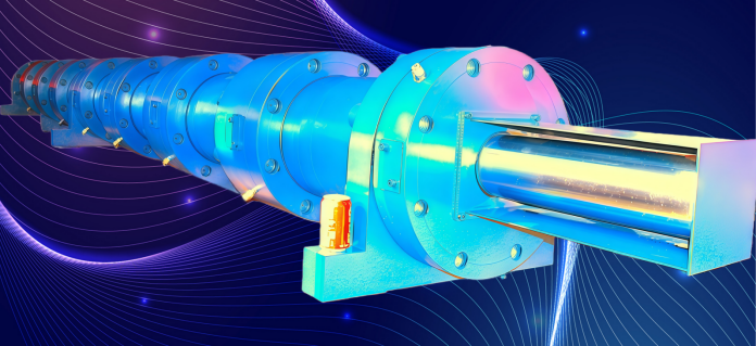
제품 적용 예시:
1. 동기 분배 유압 실린더 UF8Φ320×480P
실린더 내경: 320mm; 로드 지름: 140mm; 스트로크: 480mm 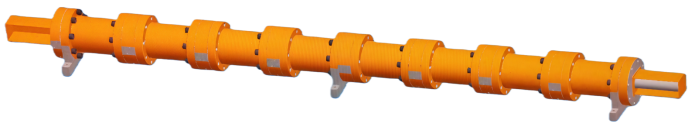
2. 동기 분배 유압 실린더 UF3Φ160×295
실린더 내경: 160mm; 로드 지름: 70mm; 스트로크: 295mm
작동 압력: 25MPa; 시험 압력: 37.5MPa 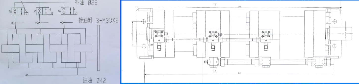
3. 동기 분배 유압 실린더 UF4Φ200/90-200LH
실린더 내경: 200mm; 로드 지름: 90mm; 스트로크: 200mm
작동 압력: 25MPa; 시험 압력: 32MPa; 작동 유체: 물 글리콜
내장된 이동 센서 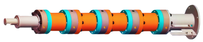
4. 동기 분배 유압 실린더 UF2Φ125×145P
실린더 내경: 125mm; 로드 지름: 50mm; 스트로크: 145mm
작동 압력: 21 MPa; 시험 압력: 31.5 MPa; 작동 유체: 유압 오일 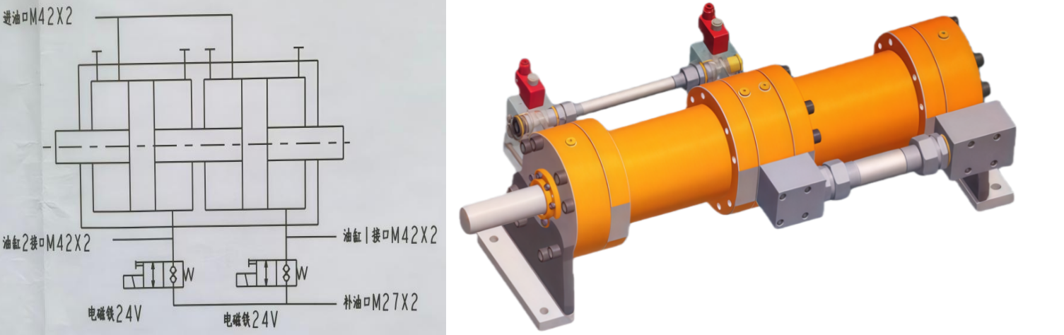


저작권 © 2024 천진 우라노스 하이드라울릭 머신 코., 리미티드.